3 minutes to help you analyze and let you understand the hydraulic system of the CNC press brake
3 minutes to help you analyze and let you understand the hydraulic system of the CNC press brake
The CNC press brake is a widely used bending machine, which has already been hydraulicized. As an important piece of sheet metal processing equipment, bending machines play an irreplaceable role and play a decisive role in product quality, processing efficiency, and accuracy.
Generally, the bending machine is an upper piston press, which is composed of a frame, a sliding block, a hydraulic system, a front support frame, a back gauge, a mold, and an electrical system, as shown in Figure 1.
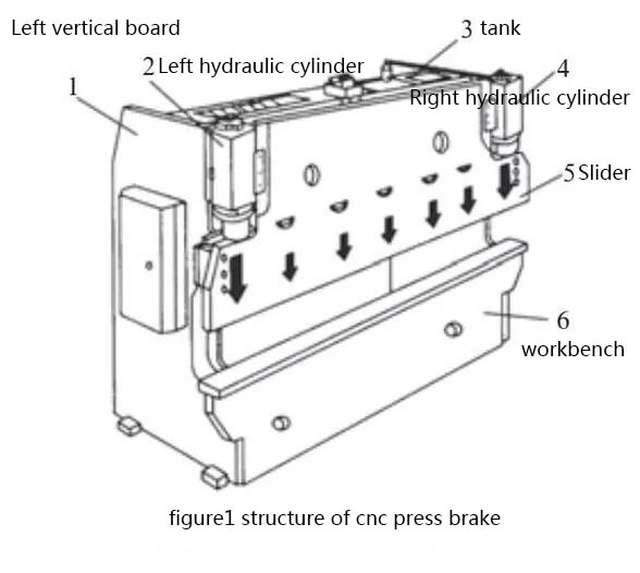
Two parallel working hydraulic cylinders form vertical downward pressure to drive the mold on the bending beam to perform bending work. As the brain of the bending machine, the hydraulic control system mainly controls the synchronous operation of the bending process and the positioning of the hydraulic cylinder when the machine is working at full load. I will take a certain type of universal bending machine as an example to analyze the hydraulic system.
Hydraulic system
Figure 2 shows the hydraulic system of the press brake. (The picture is a little fuzzy in the article, you can pay attention to my headline number, and privately write me the following text “hydraulic system”, you will receive a clear picture) Every time a bending action is performed, the typical bending process movement cycle stage of the upper bending beam include:
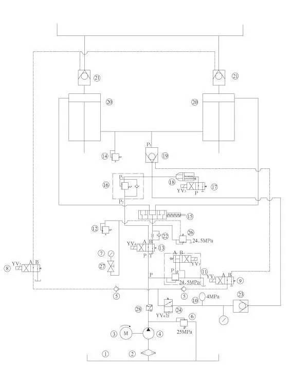
⑴Oil pump start
The motor rotates in the direction marked by the arrow of the pump, that is, clockwise, driving the axial piston pump to run. The oil enters the valve plate and the electromagnetic overflow valve return tank through the pipeline. When the No. 19 valve is closed, the No. 20 cylinder lower chamber The oil keeps the slider at a fixed position.
⑵ downward movement
The rapid downward movement of the bending machine is generated by the weight of the bending machine beam and various accessories and the pressure of the oil. During this process, the rodless cavity of the hydraulic cylinder is filled with oil through the filling valve. The rod cavity will generate back pressure and the oil will flow back quickly. The fast-forward movement starts from the top dead center. After a short deceleration stage, the speed of the slider slows down at a certain distance close to the bent sheet.
When No. 9 YV1, No. 24 YV6, No. 13 YV4, No. 17 YV5 electromagnets work, the slider quickly descends, and the descending speed is adjusted by the No. 18 valve. The oil in the lower chamber of the No. 20 cylinder passes through No. 19, No. 18, and No. 17 No. enters the oil tank, and the oil in the upper cavity of cylinder 20 is injected through the No. 21 valve.
When the slider is lowered to the limit switch, the No. 9 YV1, No. 8 YV2, No. 11 YV3, No. 13, YV4, and No. 24 YV6 electromagnets work, and the slider enters the working speed. If the slider is not synchronized, it is automatically corrected by the No. 15 valve, and the sliding position of the slider is limited by the mechanical stop in the cylinder.
⑶ bending
The bending phase starts with pressure build-up in the rodless cavity. On the one hand, the bending speed is limited by the oil supply of the oil pump, and on the other hand, it can be adjusted by the proportional valve directional valve. At the same time, the directional valve also controls the synchronous operation of the bending beam and the positioning of the bottom dead center. The limit of the bending force is accomplished by the proportional relief valve to limit the pressure of the pump. The corresponding given values of speed, synchronization, positioning and pressure all come from the CNC.
Control by foot switch or button No. 9 YV1, No. 8 YV2, No. 11
YV3, No. 13 YV4, No. 24 YV6 electromagnets work for the length of time to realize the jog distance when the slide is lowered. The speed of the slide is adjusted by the No. 16 valve, and the slide upward is controlled by the No. 11 YV3 and No. 24 YV6. The working time of the electromagnet realizes the upward jog distance of the slider.
CATEGORY AND TAGS: