Hyraulic Ironworker Machine Manual
Hyraulic Ironworker Machine Manual
Main Use
The machine is mainly used for cutting flat bar , profile, punching hole and notching. It can widely used in Shipyard,Electric,Bridge,Automobile,Hoisting& Transportation,Metal Construction and other machinery factories etc.
Performance & Features
Flat bar cutting ,punching hole and notching work can be performed on the machine within the rated specification . With extra equipment,the machine is able to cut, punch and bend in special shape . The machine adopted hydraulic driving system and has a performance and overload protecting device .
Construction
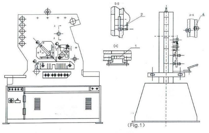
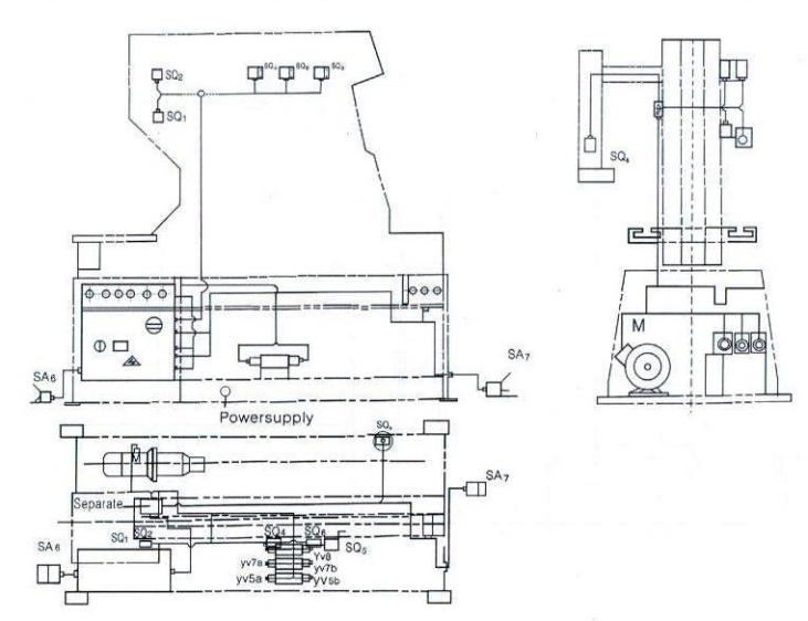
1. The bed can be seen in fig.1
The bed of the machine is composed of body,seat,bracket for section,bracket for angle and cutting table.
The body and the seat are of welded construction,others are of bolt-connected ones which give the machine great strength and rigidity and allow easy dismounting during repairing the machine.
An adjustable pad for limiting the left-right movement of the blade is mounted on the left-right housing. An adjustable hold-down for holding the angle to be cut is fitted on the angle cutting station.
With the square and round aperture of various sizes on the section cutting blade,the machine is able to cut various square and round bars.
The shearing table is fitted with a robust hold-down which is adjustable to any thickness of material and with a stop finger to allow accurate cutting of angle and flat bar at any angle.
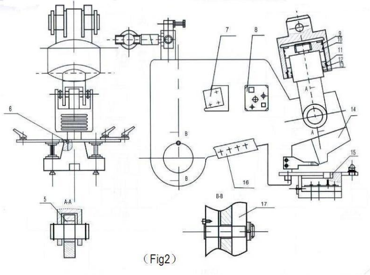
2. Section Cutting Station (Fig.2)
This station is fitted as standard with blades which is a solid structure and has four apertures to cut angle ,round ,square ,flat bars and notch steel plate .With extra toolings on the square and round bars cutting apertures channel and joist bars cutting can also be performed . The beam is connected with the oil cylinder of with the top end is hinged with the frame .Driving by the oil cylinder the beam swings to perform cutting .
The upper notching blade is fixed on the beam , There are 3lower blades which are separately fixed on the die seat with booths ,and the notching blades on both side can be adjusted to allow sufficient cutting clearance .A side gauge and a back gauge are fitted on the notching table to allow the plate to be notched on the correct position .
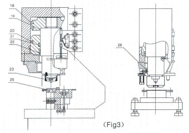
3. Punching Hole (Fig.3)
The punch is fixed on the lower end of the piston rod of the oil cylinder with locking nut and the die is fixed in the adapter .After the punch and die are aligned each other , the bolts should be tightened . To punch square and long round hole , there is a guide on the side surface of the piston rod , besides ,along round positioning slot is milled on the pad and the top of the punch to prevent the punch from being turned .With additional toolings on this station , bending ,tube notching ,louver punching ,large hole punching ,channel ,joist ,web punching work can all be performed .The max capacity of the machine is 3mm(T)×500mm(L).
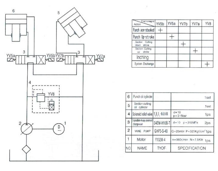
Hydraulic System
1) After the motor is started ,oil flow ,which is compressed out from the pump (1),returns to the oil tank via the solenoid valve (4) to enable the pump to be discharged .
2) By turning the mode knob to the “SINGLE” position and depressing the foot pedal for punching hole,the electromagnet YV5b is turned on , hydraulic oil flows into the top chamber of the punching unit through the valve(3),the oil in the low chamber returns to the oil tank via the valve(3), so the punch moves downward to perform punching. When the punch touches the limited switch at the lower dead point ,YV5b is turned off, the pump is set to be clischarged ,so the punch is stopped .when the foot pedal is released and YV5a is turned on ,the hydraulic oil flows to the lower chamber of the hydraulic cylinder, the punch moves upwards to touch the limited switch at the top dead point, so the YV5a is turned off and the punch is stopped at the top dead point .In the same way ,by depressing the foot pedal for cutting section, YV7b is turned on ,oil enters the top chamber of the oil cylinder for cutting section ,oil in the lower chamber returns to the oil tank via the solenoid valve(3),so the blade moves downward to perform cutting work .When the blade touchs the limit switch at the low dead point ,YV7b is turn off ,the blade is stopped at the dead point .When the foot pedal is released, YV7a is turned on ,oil enters the lower chamber in the oil cylinder for cutting cylinder ,oil in the top chamber returns to oil tank ,so the blade moves upward ,as the blade touches the limit switch at the top dead point ,it is there.
3) By turning the mode knob to the “INCHING”position and depressing the foot pedal for punching hole ,the electromagnet YV5b is turned on ,a part of hydraulic oil enters the top chamber in the oil cylinder for punching hole,
so the punch moves downward slowly .When the foot pedal is set to the middle position ,YV5a is turned off and the pump is discharged ,the punches stopped immediately . If downward continuously until it touchs the limit switch at the lower dead point . If the foot pedal is suddenly released as the punch moves downward by inching operation ,the punch will stop at any position . To drive the punch return to the SINGLE POSITION . To operate the blade for cutting section moves downward by inch meal , the operating sequence of the foot pedal is same as that above mensioned .
4) Max working pressure in the hydraulic system is 250kgf/cm 2(24.5MPa). The adjustment range of pressure in the overflow valve is 25MPa . The entire hydraulic system is protected against overload by overflow valve .
5) The machine is fitted with a pressure gauge which is used to check pressure in the hydraulic system and adjust pressure after replacing hydraulic elements . To use it ,the end screw on the valve block is removed ,mount the pressure gauge and tighten it ,then turn on the cock of the pressure gauge .
The pressure valve are shown on the gauge during operation . The pressure in the hydraulic system before delivering the machine has been properly adjusted to the delivering the machine has been properly adjusted to the max .Working value , so please do not re-adjust at your option .
Electric System
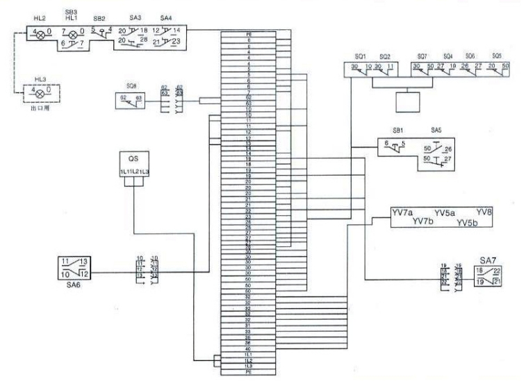
(1) Introduction:
The machine adopts the electric system of A.C 3-phase and 208/220/440V 50HZ in the main circuit and single-phase 24V and 6V comes from a transformer in control circuit and signal circuit . All electrical on an operating panel above the electrical box made by home . The section cutting station is fitted as standard with a push bottom for emergency stop.
According to the request of machine technology ,the electric system includes:
A. “NORMAL” and “JOG” working modes are selected by turning the knob SA4 .
B. Vertical stroke of punch is controlled by limit switches SQ1 and SQ2 . The section cutting upward and downward movement are separately controlled by the limit SQ4 and SQ5 ,SQ6 and SQ5 are used to control the up-move and down-move of the notching cylinder . The shift between the notching and section cutting is controlled by SA5 .
C. SQ7 is located on the top of notching part for safe protection . When you raise the safe cover ,section cutting don’t move .
D. Power supply and oil pump running are indicated HL1 and HL2 .
(2) Start and stop of Motor:
By pressing the button SB3, the motor for oil pump is started by pressing the button SB1 or SB2 ,the motor is stopped .Short circuit and over load protection are executed by an automation switch .
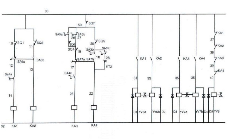
(3) Operating process:
1) Single stroke
By turning the switch SA4 to the “NORMAL” position mode and stepping the foot pedal SA6 or SA7 ,KA2 or KA4 get power ,at the same time YU5b or YU7b get power also ,so the piston for punching or the piston for section cutting moves downward . As soon as they touch the limit switch SQ2 or SQ5 ,KA1 or KA3 get power ,KA2 or KA4 lose power YU5b or YU7b are turned off ,the tow pistons stop moving downward ,simultaneously ,KA1 or KA3 turn on YV5a or YV7a turn on ,the two pistons begin to return . When they touch limit switch SQ1 ,SQ4 or SQ6 ,the return is over .
When the cylinder goes to the middle position . Release SA6 or SA7 to half position ,KA2 or KA4 lose power . YV5b or YV7b lose power the cylinder stops . When releasing the foot switch SA6 or SA7 ,it will return .
2)Lunching adjustment
By turning the switch SA4 to the “JOG” mode position and sapping the foot pedal SA6 or SA7 ,KA6 are turned on ,so the piston for punching or the pistons for section cutting and notching move downward slowly ,when they touch the limit switch SQ2 or SQ5 ,KA3 or KA6 ,YU5b or YU7b are turned off ,so two pistons stop moving downward ,when foot pedal SA6 or SA7 is released .
Two pistons can not move upward . To then return to top dead point ,the switch SA4 must be turned to the “NORMAL”mode position .
3)Back-gauge device
When putting switch SA3 to auto position ,turn the SA4 to “NORMAL”position ,putting the cutting material to back-gauge pressing the switch SQ8 . The section cutting begins to perform after the time delayer KT2 delays a few seconds when the KA5 gets power . When touching the limit switch SQ5 ,the section cutting cylinder returns to the top dead point . A cutting action is completed .
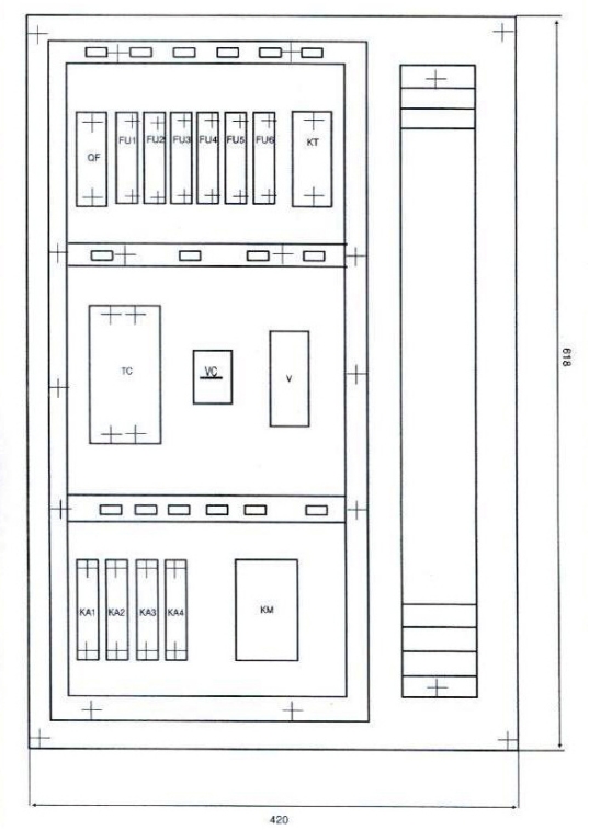
| Symbol | No.Name | Technical Data | Quantity | Type |
| SB1-2 | Push button | Red Mushroom Head | 2 | 2 XB2-BS542C |
| SB3 | Starting button | Green φ22 | 1 | XB2BW337B1C |
| SA3-5 | Limit switch | Black φ22 | 3 | XB2BD217 |
| SQ1-2 | Limit switch | / | 2 | Z-15GW22-B |
| SQ4-6 | Limit switch | / | 3 | Z-15GW22-B |
| QS | Load switch | V2 | 1 | VAR10 |
| KM1 | A.C. contactor | 24V | 1 | LC1-D3210 |
| KA1-4 | Intermediate repay | 24V 5A | 4 | MY4 |
| FU1-4 | Fuse | 6A | 4 | C45N |
| FU5-6 | Fuse | 6A | 2 | C45N |
| HL2 | Signal lamp | 24V Green | 1 | XB2-EV136 |
| VC | Silicon rectifier | 2A | 1 | KBPC20-10 |
| V | Overcurrent suppressor | / | 1 | 3TX3-221A |
| TC | Transformer | 440V 220V208V 250VA/29V 24V |
1 | JBK3-250 |
| SA6-7 | Pedal switch | SFM-1 | 2 | / |
| SQ7 | Limit switch | / | 1 | 4MC-5000 |
| QF | Motor breaker | 25-40A | 1 | GV2-M |
| SQ8 | Limit switch | / | 1 | Z-15G-B |
Hoisting ,Installation & Preparation before Trial Running
1. Hoisting
The machine is fitted with a lifting ring ,mounted on top of the machine . All lifting and manoeuvring should be carried out using this ring along with a suitably rated chain or sling . The ring can be removed if desired after final siting of the machine . Do not use chain and sling under machine .
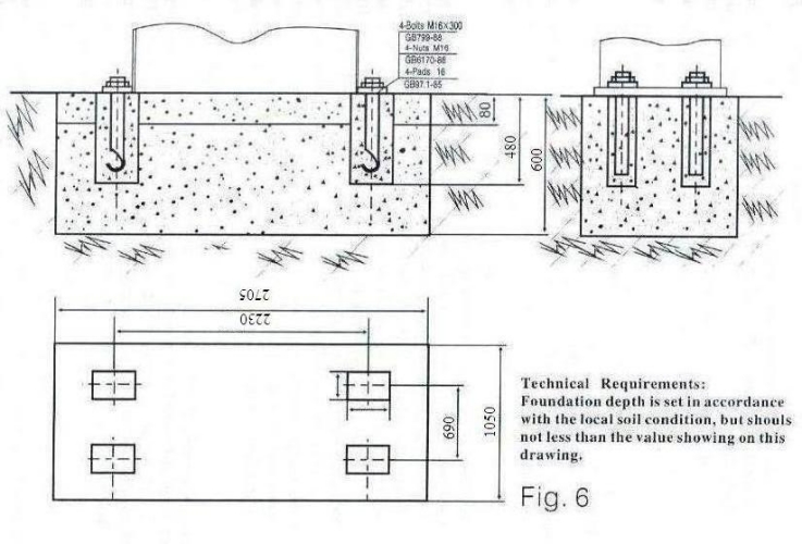
2. Installation (Fig.6)
The foundation with holes for anchor bolt should be prepared before setting the machine .Only after concrete foundation is hard set ,the machine can be set on it . Then level the machine with a level gauge ,mount anchor bolts ,our the liquid concrete into the bottom of the machine body and holes for the anchor bolts . After the concrete is hard set ,level the working table of the punching station of the machine (permissible coherence is 100:0.2) ,then tighten the anchor bolts .
3. Preparation before Trial Running
Clean and remove rust-proof grease on the die and blade of the machine ,inspect if all parts ,power supply wire and earth line are in good condition ,and all lubricating points should be lubricated .
Lubricating System
The machine adopts centralized lubricating system with manual oil gun . To increase viscosity of the lubricant ,the oil pump should be poured the 4:1 mixture of No.35 mechanical oil and calcium base grease . Operate pump 2/3 time daily to ensure enough oil in all lubricating points .
Adjustment
1. Punching
1) Adjustment of Punching Stroke (Fig.3)
There are stop blocks of upper-and lower limit switch ,which can be vertically adjusted ,on the right side of the punching station . According to the required position ,the blocks are fixed on the guide rod ,which is mounted on the piston rod and can be moved with it ,by set screw .
2) Adjustment of Punch & Die
Loosen the set screw of the die bolster and turn the knob to the “INCHING” position to make the piston rod in the punching cylinder move downward by inch meal and the punch align itself with the die ,ensure well-distributed around clearance between them . Then fix the bolster on the working table by the set screw and make the punch return to the top dead point ,so the adjustment before punching operation is finished . There are two holes for mounting dies or the bolster large hole is used for mounting the die to punch large hole on the thin plate other one is used for mounting the die to punch hole with diameter less than 30mm and for punching hole on the flange of channel and angle bar .
3) Adjustment of Hold-down Unit
The hold-down unit must be correct adjusted to allow the easy handing of materials . In general ,the distance between the bottom of the hold-down and the top of the die should be adjusted to 1.2 times the thickness of plate to be punched . To adjust hold-down ,it is only necessary to turn a nut with left or right thread connected with hole-down unit .
4) Replacement of Punch & Die
Loosen the fix nut by a wrench ,the punch can be removed . After mounting a new punch ,the nut is tightened (mounting size of the ends of various punches are the same to allow easy replacement ). Replace process of die is very easy and simple .
It is only necessary to take away an old die from the bolster hole ,the new one can be put in the hole .
2. Cutting Flat Bar
Whether cutting flat bar ,cutting profile or notching ,clearance of blade should be proper adjusted first . As shown in fig.1there are six pads (4) on the life-right housing of the machine body . By adjusting the screw and the nut on the pads ,the proper clearance of the blade between the left housing and pads can be obtained .
1) Adjustment of Blade Clearance
Adjusting screws are positioned around the stable fixing screws to support and reset the shear blades ,accessible when shear table is removed . By turning these screws ,suitable clearance between stable and movable blades will be obtained . Even clearance between them along the entire blade length should be maintained . In general this clearance should be 10% the thickness of the plate to be cut . After adjusting remount the shear table .
2) Replace Blade
Both top and bottom blade have four cutting edges . After turning blades for 4 times ,regrind or replace of new blade should be carried out . After replacing re-adjustment clearance of blades should be taken into account .
3. Angle Cutting
1) Adjustment of Blade Clearance
The angle cutting unit is fitted with a stable blade which is composed of two blades which are in square to each other . Adjusting screws are positioned around blade fixing screws to support cutting blades . By turning the adjusting screws the proper clearance between stable blade and movable blade on the carriage can be obtained .
Even clearance between stable and movable blades is important along the entire blade length and care should be taken to ensure that stable blade is parallel to movable one . This clearance ,in general ,is 10% of even thickness of angle flange to be cut .
After adjustment the angle supporter is mounted .
2) Replace Blade
Both horizontal and vertical blade of stable blade unite have four cutting edges .
Regrind or replace them with new blades after turning them for four times . The movable blade is fixed on a carriage by screws . After regrinding or replacing the blunt blades ,the blade clearance should be re-adjusted .
4. Cutting Round and Square Bar
1 ) Adjust Clearance
There are two angle shape stop blocks ,which support the stable blade and are fixed on the housing by screws ,on both side of the stable blade . Adjusting screws are positioned around the fixing screws to adjust the clearance between the angle shape stop block and the housing ,and the clearance between the supporting face nestled to the angle shape stop block and the stable blade ,and the housing . So the adjustment of clearance between the stable blade and the movable blade fixed on the carriage is carried out . After doing this ,the profile supporter is mounted .
2) Replace Blade
Remove the carriage and loosen the angle shape stop block to replace old blade with new one . After replacing clearance re-adjustment should be carried out .
5. Notching
1) Adjustment of Blade Clearance
By moving the bolster the top-end blade on ,it is set to parallel to the one on the punch to allow proper clearance ,then fix the bolster on the table by the screw .Adjusting screws are positioned around the fix screw to adjust the blades on both side of the punch ,ensuring proper clearance which is 10% of thickness of plate to be cut . After doing this the notching table is mounted .
2) Replace Blade
All there blades on the die have four edges . After replacing four times it is necessary to regrind or replace with new ones . Top blade is fixed on the punch by the screw ,loosen the screw replace old blade with new one . After replacing re-adjusting clearance should be performed .
6. Angle steel 45ºmiter cut
Angle steel 45ºmiter cut can be performed at the section position of picture (1) B-B .
Trial Running & Operation
1. Trial Running & Reparation Before Operation
1) Pour enough filtered hydraulic oil (supplied by user yourselves) into the oil tank .
2) Check if clearance of Blades is proper ,adjust it as necessary .
3) Turn on the power supply and check if action of various electrical elements are correct ,installation is proper . Push and step all push buttons ,limit switches ,foot pedal etc ,to observe of actions of electromagnet and replay are handy .
4) Star the motor to check if its running direction is correct ,pressure in the hydraulic system is in accord with the demands ,overflow pressure in the overflow valve is conform to the demands and the action of the change-over valve is handy .
2. Trial Running & Preparation
After finishing all preparation work before trial running ,the trial running and operating process can be carried out . The operating process is as follows:
1) Pushing the operating button and running on the power supply ,a green signal lamp lights to indicate that the electric system has turned on and operation can be started .
2) Starting the motor ,lubricating the top and lower chambers of punching cylinder and section cutting cylinder in order check if the punch and section cutting blade can reach the top and lower dead point .
3) Trial running in idle cycle ,test inching and single stroke for punching and section cutting in order . During testing the operation circumstances of various parts should be checked carefully . If any of them is out of order ,after clearing these troubles ,further test can be performed .
4) Pressure should be added step by step in load test . Number of performing cut or punch test in max. capacity should not less than 3 times .
Safety & Maintenance
Protect covers are proved on each station ,no hands and tools should be stretched into the cover ,besides care must be taken on following points:
1) Operator should be familiar with operation manual of the machine and possesses certain operating technique .
2) Electric insulation and earth must be in a good condition .
3) Punching and notching work must not be performed simultaneously .
4) Do not perform overload operation . (Tensile strength of material=450N/mm , hardness of material=HB180) .
5) Keep all edges of blades sharp .
6) Welding scar and burr must no be stayed on the surfaces of plate to be punched or cut .
7) To ensure safe punching and cutting work the hold-down unit should be adjusted according to any thickness of material within the cutting capacity of the machine .
8) After replacing blades ,their clearance should be re-checked ,adjust it as necessary .
9) Check connections of all parts are in good conditions regularly ,if unnormal circumstance is found the machine should be stopped to be repaired in time .
10) Lubricate all lubricating point according to working period to avoid damaging the working surfaces .
List of Wearing Parts & Parts to be Purchased
| No. | Symbol | Name | Specification | Qty |
| 9 | / | YX Shape Seal Ring | D165 | 2 |
| 10 | GB1235-76 | O Shape Seal Ring | 130×3.1 | 1 |
| 11 | GB1235-76 | -do- | 165×5.7 | 1 |
| 12 | / | YX Shape Seal Ring | d125 | 1 |
| 13 | / | Dust-proof Ring | 125 | 1 |
| 18 | / | YX Shape Seal Ring | D200 | 2 |
| 19 | GB1235-76 | O Shape Seal Ring | 135×5.7 | 2 |
| 20 | GB1235-76 | -do- | 200×5.7 | 1 |
| 21 | / | YX Shape Seal Ring | d125 | 1 |
| 17 | Sleeve | ZZnAl-6- | 1 | 0.9 |
| 4 | Friction Block | -do- | 3 | / |
| 26 | Stop Running Block | -do- | 1 | / |
List of Accessories Furnished With The Machine
| No. | Name | Specification or Type | Qty |
| 1 | Foot Pedal | Y13-11 | 2pcs |
| 2 | Key to the Interlocking | Device | 2pcs |
| 3 | Hexagon Key Wrench | S=3-19 | 1set |
| 4 | Hook Shape Wrench | D=90-95 | 1pc. |
| 5 | Discharge Cock | / | 1pc. |
| 6 | Manometer Unit | / | 1set. |
| 7 | O Shape Seal Ring | 130×3.1(GB1235-76) | 1pc. |
| 8 | -do- | 165×5.7(GB1235-76) | 1pc. |
| 9 | -do- | 200×5.7(GB1235-76) | 1pc. |
| 10 | -do- | 135×5.7(GB1235-76) | 2pcs |
| 11 | Dust-proof Ring | 125 | 2pcs |
| 12 | SF-1 Bearing of Compound Material | 5560(SF-1) | 1pc. |
| 13 | Oil gun | Capacity:200cm³ | 1 |
—End
CATEGORY AND TAGS: