sheet metal bending formation

Analysis of the relationship between bending formation and grooving process

Analysis of the relationship between bending formation and grooving process


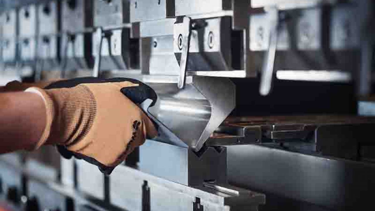
The traditional bending process is to use the two edges at the opening of the lower die and the top edge of the upper die to bend the metal sheet under the pressure of the upper and lower molds of the NC press brake. The sheet metal undergoes elastic deformation to plastic deformation. The bending angle is determined by the depth of the upper mold entering the lower mold. In today’s society, people have higher and higher requirements for the shape of the workpiece. Some workpieces with complex shapes can no longer be bent using traditional free bending, bending machine bending or even three-point bending technology, and traditional bending methods cannot control the bending. The radius of the rounded corners makes it difficult to achieve the process requirements for seamless bending. Therefore, a new type of bending process-grooving bending process came into being.

It can be seen from the bending process that the size of the edge arc radius of the workpiece after bending is in direct proportion to the thickness of the sheet. The thicker the sheet, the larger the radius of the arc formed by bending. After V-grooving the metal sheet, the remaining thickness of the sheet becomes half of the original thickness, or even smaller, so that the edge arc radius after the workpiece is bent can be greatly reduced. In addition, since the remaining thickness of the bend is thinner after grooving, the deformation force during bending will be reduced accordingly, and will not spread to the unbent area. Therefore, there are no creases on the surface of the workpiece after bending, and due to bending The thickness of the board is thinner, and the pressure required during bending is reduced to avoid the risk of indentation on the decorative surface. In this way, the metal decoration of high-end places such as hotels, banks, commercial centers, airports, etc., has a small arc radius of the workpiece edge, no creases on the surface, and no indentation on the decorative surface.

In the bending process, the required bending force of the sheet metal is proportional to its thickness. The greater the thickness of the sheet metal, the greater the bending force required, and the required equipment tonnage increases accordingly. After V-shaped grooving is performed on the bending part of the sheet metal before bending, the remaining thickness of the sheet at that place is greatly reduced, so that the bending force required when the sheet is bent will also be correspondingly reduced, so that the thick plate can be in a smaller tonnage Bending on the bending machine. This not only reduces the investment in equipment, but also saves energy and space.

How to avoid the deviation of bending angle and size

For the bending process, the quality of bending mainly depends on the two important parameters of bending angle and size. When bending, in order to ensure the forming size and angle of the bending, the following issues need to be paid attention to.

⑴ The upper and lower molds are not aligned with each other, which will cause errors in the bending dimensions. The upper and lower mold tools need to be aligned before bending.

⑵ After the left and right positions of the rear stopper are moved, the relative position of the sheet metal and the lower die may change, which will affect the bending size. The position distance of the rear stopper must be re-measured before bending.

(3) Insufficient parallelism between the workpiece and the lower die will cause bending springback and affect the bending angle. The parallelism must be measured and adjusted before bending.

⑷ When the angle of the first bending is insufficient, the second bending will also be affected. The accumulation of bending errors will increase the forming size and angle errors of the workpiece. Therefore, it is particularly important to ensure the accuracy of single-sided bending.

⑸When bending, the size of the lower die V port is inversely proportional to the bending pressure. When processing metal plates of different thicknesses, you need to select the appropriate lower die V-groove according to the regulations. Generally, 6-8 times the plate thickness is the most appropriate .

⑹ When the workpiece is bent on the bending machine after planing the V-shaped groove, ensure that the edge of the upper die, the bottom edge of the V-shaped groove of the workpiece and the bottom edge of the V-shaped groove of the lower die are on the same vertical surface.

⑺ When bending the workpiece after grooving, in order to prevent knife clamping, the upper die angle is best controlled at about 84°.

grooving process, as a new type of bending process, is the result of market choice. With the continuous development of process technology, enterprises have higher and higher requirements for process personnel. As craftsmen, only by mastering various processing techniques can we produce better products; only by constantly exploring and pursuing new techniques can we produce better products.

hydraulic system

3 minutes to help you analyze and let you understand the hydraulic system of the CNC press brake

3 minutes to help you analyze and let you understand the hydraulic system of the CNC press brake


The CNC press brake is a widely used bending machine, which has already been hydraulicized. As an important piece of sheet metal processing equipment, bending machines play an irreplaceable role and play a decisive role in product quality, processing efficiency, and accuracy.

Generally, the bending machine is an upper piston press, which is composed of a frame, a sliding block, a hydraulic system, a front support frame, a back gauge, a mold, and an electrical system, as shown in Figure 1.

Two parallel working hydraulic cylinders form vertical downward pressure to drive the mold on the bending beam to perform bending work. As the brain of the bending machine, the hydraulic control system mainly controls the synchronous operation of the bending process and the positioning of the hydraulic cylinder when the machine is working at full load. I will take a certain type of universal bending machine as an example to analyze the hydraulic system.

Hydraulic system

Figure 2 shows the hydraulic system of the press brake. (The picture is a little fuzzy in the article, you can pay attention to my headline number, and privately write me the following text “hydraulic system”, you will receive a clear picture) Every time a bending action is performed, the typical bending process movement cycle stage of the upper bending beam include:

⑴Oil pump start

The motor rotates in the direction marked by the arrow of the pump, that is, clockwise, driving the axial piston pump to run. The oil enters the valve plate and the electromagnetic overflow valve return tank through the pipeline. When the No. 19 valve is closed, the No. 20 cylinder lower chamber The oil keeps the slider at a fixed position.

⑵ downward movement

The rapid downward movement of the bending machine is generated by the weight of the bending machine beam and various accessories and the pressure of the oil. During this process, the rodless cavity of the hydraulic cylinder is filled with oil through the filling valve. The rod cavity will generate back pressure and the oil will flow back quickly. The fast-forward movement starts from the top dead center. After a short deceleration stage, the speed of the slider slows down at a certain distance close to the bent sheet.

When No. 9 YV1, No. 24 YV6, No. 13 YV4, No. 17 YV5 electromagnets work, the slider quickly descends, and the descending speed is adjusted by the No. 18 valve. The oil in the lower chamber of the No. 20 cylinder passes through No. 19, No. 18, and No. 17 No. enters the oil tank, and the oil in the upper cavity of cylinder 20 is injected through the No. 21 valve.

When the slider is lowered to the limit switch, the No. 9 YV1, No. 8 YV2, No. 11 YV3, No. 13, YV4, and No. 24 YV6 electromagnets work, and the slider enters the working speed. If the slider is not synchronized, it is automatically corrected by the No. 15 valve, and the sliding position of the slider is limited by the mechanical stop in the cylinder.

⑶ bending

The bending phase starts with pressure build-up in the rodless cavity. On the one hand, the bending speed is limited by the oil supply of the oil pump, and on the other hand, it can be adjusted by the proportional valve directional valve. At the same time, the directional valve also controls the synchronous operation of the bending beam and the positioning of the bottom dead center. The limit of the bending force is accomplished by the proportional relief valve to limit the pressure of the pump. The corresponding given values of speed, synchronization, positioning and pressure all come from the CNC.

Control by foot switch or button No. 9 YV1, No. 8 YV2, No. 11

YV3, No. 13 YV4, No. 24 YV6 electromagnets work for the length of time to realize the jog distance when the slide is lowered. The speed of the slide is adjusted by the No. 16 valve, and the slide upward is controlled by the No. 11 YV3 and No. 24 YV6. The working time of the electromagnet realizes the upward jog distance of the slider.

plate rolling machine structure

How the internal structure of the sheet metal rolling machine is designed?

How the internal structure of the sheet metal rolling machine is designed?


Do you know how the internal structure of the sheet metal rolling machine is designed? There are many types of rolling machines, how many parts do they have in their internal structure, and how are these parts designed?

One

Take symmetrically adjusted three-roll sheet metal rolling machine as an example. The two lower rollers are active rollers with fixed positions, and the upper roller is a movable roller that can move up and down. With the help of the clutch, the upper roller can be adjusted to the parallel or inclined position with respect to the lower roller to meet the needs of rolling round or conical workpieces. Three rollers are installed on the left and right frames to form the main body of the machine. The transmission system is all arranged on the right side of the right frame, and the frame and the transmission part are arranged on the integral welded base to form the main body of the machine. The electric control console is located in front of the machine. In order to indicate the up-and-down displacement of the upper roller, pointers and scales are set on the right frame and the bearing. In order to facilitate the removal of the cylindrical workpiece from the upper roller, a turning bearing is provided at the left end of the upper roller, and a tilting adjustment structure is provided at the right end.


The positive and negative rotation of the lower roller, the lifting, tilting, and leveling of the upper roller are controlled by electrical appliances, the disengagement and closing of the flip bearing of the discharge, the position adjustment of the tilting adjustment mechanism, and the clutch clutch are all manually operated.

Therefore, the three-roller sheet metal rolling machine with this structure, because the position of the two lower rollers is fixed and is always symmetrical to the upper roller, the remaining straight side of the end of the workpiece that is directly rolled by it is long, so you need to use special tools or Other equipment pre-bends the end to make up for this deficiency.

Because of its simple structure, reliable work, and easy maintenance, it is widely used in other production of medium plate tubes.

Two

The two lower rollers of the sheet metal rolling machine are the driving rollers, which are transmitted by the main motor through the three-stage transmission pair of the arc gear reducer with a ratio of 62.2 to the first-stage open gear pair supported by the lower roller, so that the lower roller The design rotation speed is obtained and constitutes the main transmission system of the machine. There is a brake in the main drive system to achieve rapid braking.

The lifting movement of the upper roller is decelerated by the auxiliary motor through the secondary transmission pair of the auxiliary circular arc gear reducer with a ratio of 12, which drives the worm gear pair installed in the frame to rotate, and the wire sleeve embedded in the wheel rotates to force the connection to the upper roller.The lifting screw rod moves linearly, forming the auxiliary system of the machine. The adjustment of the relative position of the two ends of the upper roller with respect to the lower roller is realized by separately lifting the lifting screw Hodder at the left end after disengaging the clutch on the worm shaft.

The upper roller of the sheet metal rolling machine is the active roller. The main motor drives the upper roller to work through the main reducer and coupling. The function of the lower roller is to provide a certain upward force to clamp the rolled steel plate together with the upper roller to make Sufficient friction is generated between the upper roller and the coiled steel plate, which can drive the steel plate to move when the upper roller rotates. The two side rollers are used to form the required curvature of the roll, so that the sheet can achieve the required purpose.

Three

In the four-roller sheet metal rolling machine we designed, we used the main motor through the main reducer and coupling to drive the upper roll to rotate. For the movement of the lower roller, we put a hydraulic cylinder on each end of the lower roller, and the hydraulic oil in the hydraulic cylinder acts on the piston so that the lower roller can move up and down, so that the steel plate can be clamped and controlled by the hydraulic system. The lifting of the roller and the two hydraulic cylinders keep rising synchronously during the ascending process. There are two side rollers on both sides of the lower roller. The two side rollers are respectively driven by two motors through two single-stage reducers and couplings; the two motors can be controlled separately or simultaneously. The two side rollers It can be tilted along the guide rails of the frame and driven by a worm gear and a screw nut.

NC press brake

Purchase knowledge of hydraulic bending machine|CNC bending machine

Purchase knowledge of hydraulic bending machine|CNC bending machine


There are 6 points need to considerate when you buy a hydraulic bending machine.


  • Artifact

The first important thing to consider is the parts you want to produce. The point is to buy a machine that can complete the processing task with the shortest workbench and the smallest tonnage.

Carefully consider the material grade and the maximum processing thickness and length. If most of the work is low carbon steel with a thickness of 16 gauge and a maximum length of 10 feet, then the free bending force does not need to be greater than 50 tons. However, if you are engaged in a large number of bottomed die forming, perhaps a 150-ton machine tool should be considered. Assuming that the thickest material is 1/4 inch, 10 feet free bending requires 165 tons, and bottomed die bending (correction bending) requires at least 600 tons. If most of the workpieces are 5 feet or shorter, the tonnage is almost halved, which greatly reduces the purchase cost. The length of the part is very important for determining the specifications of the new machine.


  • Torsion

Under the same load, the deflection of the worktable and sliding block of the 10-foot machine is 4 times that of the 5-foot machine. This means that shorter machines require fewer shim adjustments to produce qualified parts. Reduced shim adjustment and shortened preparation time. Material grade is also a key factor. Compared with low-carbon steel, the load required for stainless steel is usually increased by about 50%, while most grades of soft aluminum are reduced by about 50%. You can get the machine’s tonnage table from the bending machine manufacturer at any time. The table shows the estimated tonnage required per foot in different thicknesses and different materials.


  • The bending radius of the part

When using free bending, the bending radius is 0.156 times of the die opening distance. During the free bending process, the opening distance of the die should be 8 times the thickness of the metal material. For example, when forming mild steel with an opening distance of 1/2 inch, the bending radius of the part is about 0.078 inches. If the bending radius is almost as small as the material thickness, a bottomed die must be formed. However, the pressure required for forming a bottomed die is about 4 times greater than that of free bending.

If the bending radius is less than the thickness of the material, a punch with a front-end fillet radius smaller than the thickness of the material must be used, and the imprint bending method must be used. In this way, 10 times the pressure of free bending is required.

As far as free bending is concerned, punch and die are processed at 85° or less. When using this set of molds, pay attention to the gap between the punch and the die at the bottom of the stroke, and the excessive bending that is sufficient to compensate for the springback and keep the material at about 90°.

Generally, the springback angle of the free bending die on the new bending machine is ≤2°, and the bending radius is equal to 0.156 times the opening distance of the die.

For the bending of bottomed concave mold, the mold angle is generally 86 ~ 90°. At the bottom of the stroke, there should be a gap slightly larger than the thickness of the material between the male and female molds. The forming angle is improved because the bottomed die has a larger bending tonnage (about 4 times that of free bending), which reduces the stress that usually causes springback in the bending radius.

The imprint bending is the same as the bending of the bottomed die, except that the front end of the punch is processed to the required bending radius, and the gap between the punch and the die at the bottom of the stroke is smaller than the material thickness. Since enough pressure (approximately 10 times of free bending) is applied to force the front end of the punch to contact the material, springback is basically avoided.

In order to select the lowest tonnage specification, it is best to plan for a bending radius larger than the material thickness and use the free bending method as much as possible. When the bending radius is large, it often does not affect the quality of the part and its future use.


  • Precision

Bending accuracy requirements are a factor that needs to be carefully considered. It is this factor that determines whether you need to consider a CNC bending machine or a manual bending machine. If the bending accuracy requires ±1° and it cannot be changed, you must focus on the CNC machine.

The repeatability of the slider of the CNC bending machine is ±0.0004 inches, and the precise angle of forming must use such precision and a good mold. The repeatability of the slide block of the manual bending machine is ±0.002 inches, and the deviation of ±2~3° is generally produced under the condition of using a suitable mold. In addition, the CNC bending machine is prepared for rapid mold assembly. When you need to bend many small batches of parts, this is an indisputable reason for consideration.


  • Mould

Even if you have shelves full of molds, don’t assume that these molds are suitable for the newly purchased machine. The wear of each mold must be checked by measuring the length from the front end of the punch to the shoulder and the length between the shoulder of the female mold.
For conventional molds, the deviation per foot should be about ±0.001 inches, and the total length deviation should not exceed ±0.005 inches. As for the precision grinding mold, the accuracy per foot should be ±0.0004 inches, and the total accuracy should not be greater than ±0.002 inches. It is best to use fine grinding molds for hydraulic bending machines, and conventional molds for manual bending machines.


  • Side length of bending part

Assuming that it is bent 90° along a 5×10-foot mild steel plate, the bending machine must apply an additional 7.5 tons of pressure to lift the steel plate, and the operator must prepare for the 280-pound straight-edge drop. It may require several strong workers or even a crane to manufacture this part. Operators of bending machines often need to bend long-side parts without realizing how hard their work is.

Nowadays, there is a kind of supporting device suitable for workshops engaged in this kind of work. This kind of device can be improved according to the needs of new and old machines. With this device, only one person is required to form long-side parts.