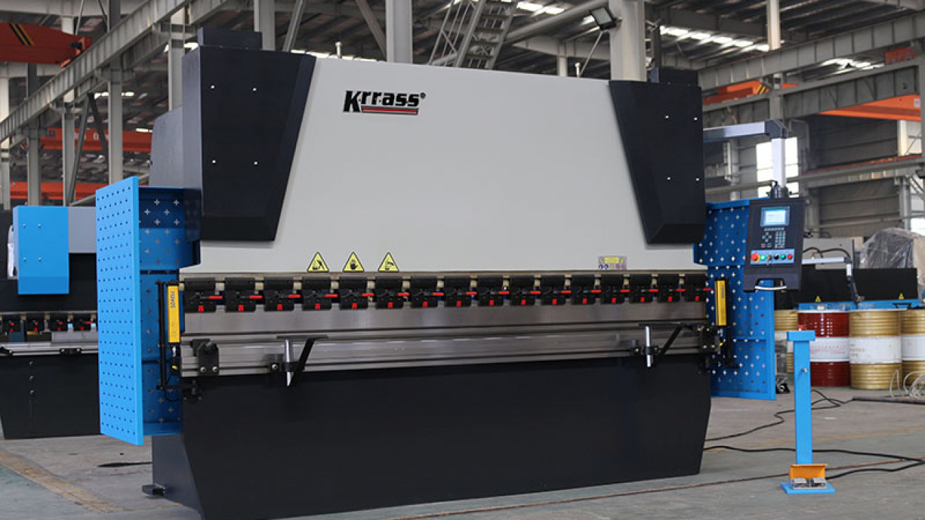
What is CNC press brake?
CNC press brake is a kind of machine which can bend thin plates. Its structure mainly includes bracket, worktable and clamping plate. The worktable is placed on the bracket. The worktable is composed of a base and a pressing plate. The base is connected with the clamping plate through hinges. The base is composed of a base shell, a coil and a cover plate. The coil is placed in the depression of the base shell, and the top of the depression is covered with a cover plate. When in use, the coil is electrified by the wire, and the pressing plate is attracted after being electrified, so as to realize the clamping of the thin plate between the pressing plate and the base. Due to the use of electromagnetic force clamping, the pressing plate can be made into a variety of workpiece requirements, and the workpiece with side wall can be processed, and the operation is very simple.

Working principle of CNC press brake:
The hydraulic CNC press brake includes a bracket, a worktable and a clamping plate. The worktable is placed on the bracket, and the worktable is composed of a base and a pressing plate. The base is connected with the clamping plate through a hinge. The base is composed of a base shell, a coil and a cover plate. The coil is placed in the depression of the base shell, and the top of the depression is covered with a cover plate.
When in use, the coil is electrified by the wire, and the pressing plate is attracted after being electrified, so as to realize the clamping of the thin plate between the pressing plate and the base. Due to the use of electromagnetic force clamping, the pressing plate can be made into a variety of workpiece requirements, and the workpiece with side wall can be processed. CNC press brake can meet the needs of various workpieces by replacing CNC press brake mold.
Classification of CNC press brake:
CNC press brake is divided into manual CNC press brake, hydraulic CNC press brake and CNC press brake. Manual CNC press brake can be divided into mechanical CNC press brake and electric manual CNC press brake. Hydraulic CNC press brake can be divided into torsion shaft synchronization, mechanical hydraulic synchronization and electro-hydraulic synchronization according to synchronization mode. According to the movement mode, hydraulic CNC press brake can be divided into up moving type and down moving type.
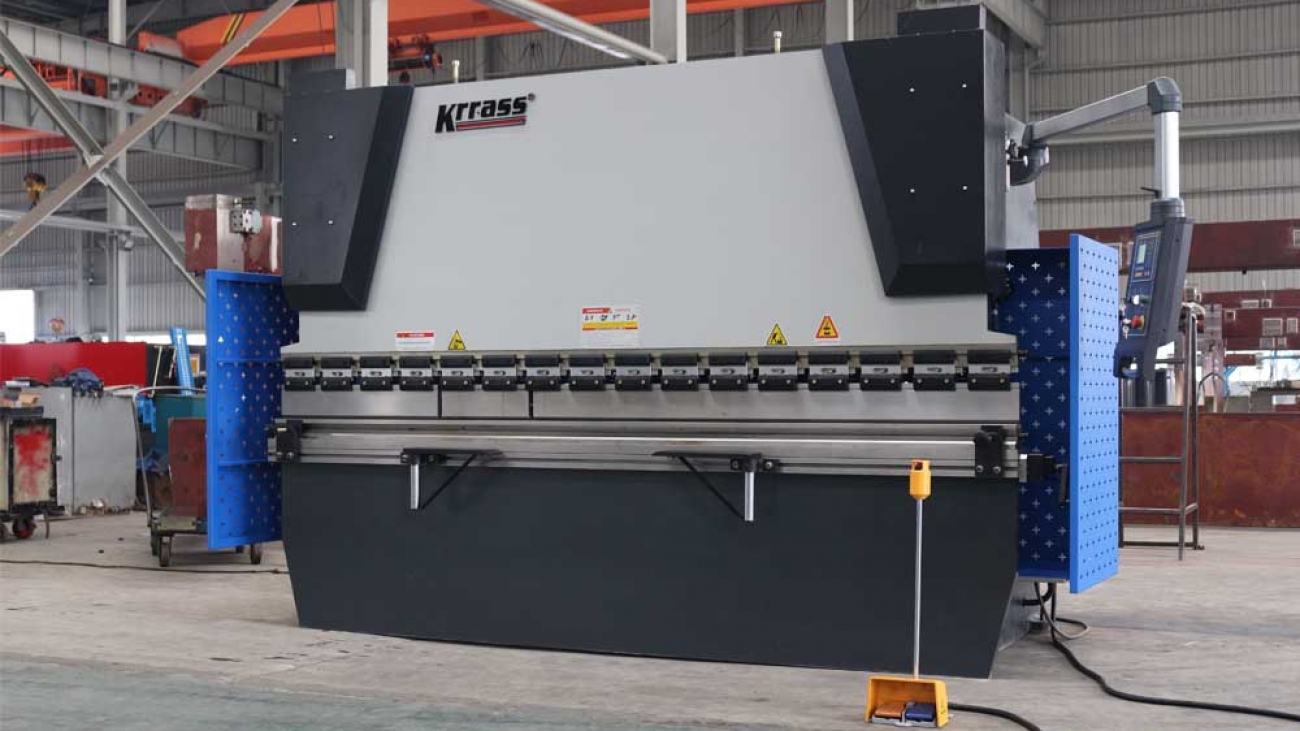
Structural description of CNC press brake:
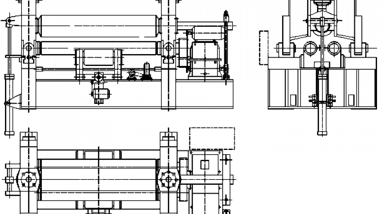
CNC press brake is an important equipment in sheet metal industry. Its function is to press the steel plate into various shapes according to the process requirements. As shown in the figure is the hydraulic plate CNC press The brake structure diagram is mainly composed of left and right columns, worktable and crossbeam. The left and right oil cylinders are fixed on the column. The sliding block is connected with the piston of the oil cylinder and moves up and down along the guide rail fixed on the column. The lower die is fixed on the workbench, and the upper mold is installed at the lower end of the slide block. The hydraulic pressure system provides power and the electrical system gives instructions. Under the action of the oil cylinder, the slider drives the upper die The lower die is closed with the lower die to realize the bending of sheet metal. The left and right columns, worktable and slide block (hereinafter referred to as the three major parts) are the key parts of CNC press brake. The sum of the three parts accounts for 70% ~ 80% of the total weight of a CNC press brake. Its strength and rigidity directly determine the operation accuracy, service life and the accuracy of the workpiece.
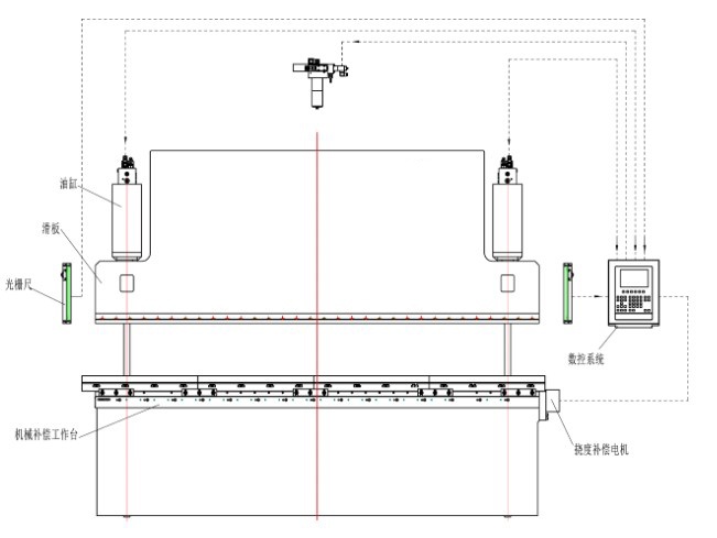
- Slider part: hydraulic transmission, the slider part is composed of slider, oil cylinder and mechanical block fine-tuning structure. The left and right cylinders are fixed on the frame, and the piston (rod) drives the slider to move up and down by hydraulic pressure, and the mechanical block is controlled and adjusted by the numerical control system;
- Worktable part: controlled by button box, the motor drives the material retaining frame to move forward and backward, and the distance is controlled by the CNC system. The minimum reading is 0.01mm (there are travel switch limits in the front and back positions);
- Synchronization system: the machine is composed of torsion shaft, swing arm and joint bearing. It has simple structure, stable and reliable performance and high synchronization accuracy. The mechanical block is adjusted by the motor, and the numerical control system controls the value;
- Blocking mechanism: the blocking material is driven by motor, and the two screw rods are driven to move synchronously through chain operation, and the size of blocking material is controlled by numerical control system.
The structural features of CNC press brake are as follows:
- All steel welding structure is adopted, which has enough strength and rigidity;
- Hydraulic transmission, the oil cylinders at both ends of the machine tool are placed on the slide block to directly drive the sliding work;
- The slider synchronous mechanism adopts torsion shaft forced synchronization;
- Mechanical block structure is adopted, which is stable and reliable;
- The slide stroke can be adjusted quickly and manually, and the counter is displayed;
- Wedge type deflection compensation mechanism to ensure high bending accuracy.
How to use CNC press brake:
According to the common hydraulic CNC press brake processing
Q235 sheet metal to do a brief introduction:
- First, turn on the power, turn on the key switch on the control panel, and then press the oil pump to start.
- Travel adjustment, the use of CNC press brake must pay attention to adjust the stroke, before bending must be trial run. When the upper die of CNC press brake goes down to the bottom, there must be a gap of plate thickness. Otherwise, the mould and machine will be damaged. The stroke adjustment also has the electric quick adjustment and the manual fine adjustment.
- Bending notch selection, generally to choose the plate thickness of 8 times the width of the notch. If bending 4mm sheet, the notch of about 32 should be selected.
- Generally, there are electric quick adjustment and manual fine adjustment for the adjustment of rear stop, and the method is the same as that of plate shears.
- Press the foot switch to start bending. Unlike the shearing machine, CNC press brake can be released at any time. Release the foot and stop the CNC press brake, and then step on it to continue downward.
Purchase of CNC press brake:
When choosing CNC press brake improperly, the production cost will rise, and the cost of CNC press brake can not be expected to recover. Therefore, several factors need to be considered in decision-making.
workpiece
The first important thing to consider is the parts you want to produce. The point is to buy a machine that can complete the processing task with the shortest worktable and the smallest tonnage.
Carefully consider the material grade and the maximum machining thickness and length. If most of the work is 16 gauge mild steel with a maximum length of 10 feet (3.048 meters), the free bending force does not have to be greater than 50 tons. However, if you are engaged in a large number of bottomed die forming, maybe a 160 ton machine tool should be considered.
Assuming the thickest material is 1 / 4 inch, 200 tons are required for 10 foot free bending, and at least 600 tons are required for bottom die bending (correction bending). If most of the work pieces are 5 feet or less, the tonnage is almost halved, which greatly reduces the purchase cost. The length of the parts is very important to the specification of the new machine.
Deflection
Under the same load, the deflection of the table and slide block of the 10 foot machine is 4 times that of the 5-foot machine. This means that shorter machines require less shimming to produce qualified parts. The reduction of gasket adjustment shortens the preparation time.
Material grade is also a key factor. Compared with low carbon steel, the load required for stainless steel is usually increased by about 50%, while the soft aluminum of most brands is reduced by about 50%. At any time, you can get the tonnage table of the machine from the manufacturer of CNC press brake, which shows the estimated tonnage required per foot of length for different thicknesses and materials.
Bending radius
When free bending is adopted, the bending radius is 0.156 times of the die opening distance. In the process of free bending, the die opening distance should be 8 times of the metal thickness. For example, when 1 / 2 inch (0.0127 m) opening distance is used to form 16 gauge mild steel, the bending radius of the part is about 0.078 inch. If the bending radius is almost as small as the thickness of the material, a bottomed die is required. However, the pressure required for forming a bottomed die is about four times greater than that for free bending.
If the bending radius is less than the material thickness, the punch with the front fillet radius less than the material thickness should be used, and the stamping bending method should be used. In this way, 10 times the free bending pressure is required.
As far as free bending is concerned, punch and die should be processed at 85 ° or less (small point is better). When using this group of dies, pay attention to the gap between punch and die at the bottom of the stroke, and the excessive bending enough to compensate for springback and keep the material about 90 degrees.
Generally, the springback angle of the free bending die on the new CNC press brake is less than 2 ° and the bending radius is equal to 0.156 times of the die opening distance. For bending with bottom die, the die angle is generally 86 ~ 90 °. At the bottom of the stroke, there should be a gap slightly larger than the material thickness between the punch and die. The forming angle is improved because the bending tonnage of bottomed die is large (about 4 times of free bending), which reduces the stress which usually causes springback within the bending radius.
Stamping bending is the same as bending with bottom die, but the front end of punch is processed to the required bending radius, and the gap between punch and die at the bottom of stroke is less than the material thickness. Since sufficient pressure (about 10 times of free bending) is applied to force the front end of the punch to contact the material, springback is basically avoided.
In order to select the lowest tonnage size, it is better to plan for the bending radius greater than the thickness of the material, and the free bending method should be adopted as far as possible. When the bending radius is large, the quality of the finished part and its use in the future are not affected.
Curvature
The bending accuracy requirement is a factor that needs to be carefully considered. It is this factor that determines whether a CNC press brake or a manual CNC press brake should be considered. If the bending accuracy requires ± 1 ° and cannot be changed, the CNC machine must be focused.
The repeatability accuracy of cnccnc press brake slider is ± 0.0004 inch, so the precision and good die must be used for the accurate forming angle. The repeatability accuracy of manual CNC press brake slider is ± 0.002 inch, and the deviation of ± 2 ~ 3 ° is generally produced under the condition of proper mold. In addition, cnccnc press brake is ready for rapid tooling, which is an indisputable reason to consider when many small batch parts need to be bent.
mould
Even if there are full shelves of molds, do not think that these molds are suitable for newly purchased machines. Each die must be checked for wear by measuring the length from the front end of the punch to the shoulder and between the shoulder of the female die.
For conventional dies, the deviation per foot should be about ± 0.001 inch, and the total length deviation should not be more than ± 0.005 inch. For precision grinding dies, the accuracy per foot should be ± 0.0004 inches, and the total accuracy should not be greater than ± 0.002 inches. It is better to use fine grinding die for CNC press brake and conventional mold for manual CNC press brake.
Side length of bending part
Assuming a 90 ° bend along a 5 × 10 foot 10 gauge mild steel plate, the CNC press brake will have to apply an additional 7.5 tons of pressure to lift the plate, and the operator must be prepared for a 280 pound straight edge drop.