200ton Hydraulic Ironworker for sale

200ton Ironworker,Q35Y-40 Hydraulic Ironworker Machine Supplier from China

200ton Ironworker,Q35Y-40 Hydraulic Ironworker Machine Supplier from China


Main functions

1)2 independent hydraulic piston rods and foot-pedal allows two people operating at the same time.

2)More efficient stroke-control functions of piston rod.

3)Central lubricating system

4)Motor-driven rear stopper

5)Lighting devices for work

6)5 independent work-positions: punch pin and die (standard punching dies),cutting blade group for round and square steel, shearing blades for steel plate, slotting and angle-cutting blade.]

ElectricsSchneider – France
Main motorSiemens – Germany
Oil pumpSUNNY – USA
Valve blockRexroth – Germany
Pedal switchKACON – South Korea
Wind-cooler for oilChina

Sealing ring

Parker – USA
Oil pipe connectorpressure hose – Germany
Safety guard

KRRASS


Technical Parameters

Technical Specifications Q35Y-40
Punching Pressure(T) 200T
Depth of throat(mm) 600s

Featurespunching holesDiameter*Max. thicknessmm40X35
Diameter*thicknessmm40X35
Max.diametermm40
Strokemm80
Work strokemmX35
Throat Depthmm600
Steel bar cuttingRound steelmm70
Square steelmm60X60
Angel cuttingAngle cuttingmm200X200X18
Angle°Dgree100X100X10
Edged surfacemm12
SlottingThicknessmm300
Widthmm89
Depthmm
         U-shaped and I-beam cuttingmm160X160X14
T-section cuttingmm80X80X10
I-beam cuttingmm300X126X11
V-slotting diemm600
V-bendingmm33
Pressurekn2000
Motor Powerkw18.5
Weightkg11000
Machine outline size(LXWXH)mm2970X1240X2350


200ton Hydraulic Ironworker for sale

160ton Ironworker,Q35Y-30 Hydraulic Ironworker Machine for Metal Fabrication

160ton Ironworker,Q35Y-30 Hydraulic Ironworker Machine for Metal Fabrication


Krrass Q35Y-30 160ton ironwoker machine for sale, high-quality with factory price.Any interest, please free contact us.

Main Functions

1)2 independent hydraulic piston rods and foot-pedal allows two people operating at the same time.

2)More efficient stroke-control functions of piston rod.

3)Central lubricating system

4)Motor-driven rear stopper

5)Lighting devices for work

6)5 independent work-positions: punch pin and die (standard punching dies),cutting blade group for round and square steel, shearing blades for steel plate, slotting and angle-cutting blade.


Main Configurations

NO.ItemManufacturer
1-ElectricsSchneider – France
2-Main motorSiemens – Germany
3-Oil pumpSUNNY – USA
4-Valve blockRexroth – Germany
5-Pedal switchKACON – South Korea
6-Wind-cooler for oilChina
7-Sealing ringParker – USA
8-Oil pipe connectorpressure hose – Germany
9-Safety guardKRRASS


Technical SpecificationsQ35Y-30
Punching Pressure(T)160T
Depth of throat(mm)600


Featurespunching holesDiameter*Max. thicknessmm38X26
Diameter*thicknessmm38X26
Max.diametermm38
Strokemm80
Work strokemmX30
Throat Depthmm600
Steel bar cuttingRound steelmm65
Square steelmm55X55
Angel cuttingAngle cuttingmm180X180X16
Angle°Dgree60X60X6
Edged surfacemm11.5
SlottingThicknessmm280
Widthmm86
Depthmm
         U-shaped and I-beam cuttingmm180X180X16
T-section cuttingmm80X80X10
I-beam cuttingmm280X124X10.5
V-slotting diemm600
V-bendingmm26
Pressurekn1600
Motor Powerkw15
Weightkg6800
Machine outline size(LXWXH)mm2680X1040X2300
200ton Hydraulic Ironworker for sale

120T Ironworker Machine,Q35Y-25 Sheet Metal Ironworker For Sale

120T Ironworker Machine,Q35Y-25 Sheet Metal Ironworker For Sale


Main functions

1)2 independent hydraulic piston rods and foot-pedal allows two people operating at the same time.

2)More efficient stroke-control functions of piston rod.

3)Central lubricating system

4)Motor-driven rear stopper

5)Lighting devices for work

6)5 independent work-positions: punch pin and die (standard punching dies),cutting blade group for round and square steel, shearing blades for steel plate, slotting and angle-cutting blade.


Parameters

Technical SpecificationsQ35Y-25
Punching Pressure(T)120T
Depth of throat(mm)400
Featurespunching holesDiameter*Max. thicknessmm35X25
Diameter*thicknessmm35X25
Max.diametermm35
Strokemm80
Work strokemmX25
Throat Depthmm400
Steel bar cuttingRound steelmm60
Square steelmm50X50
Angel cuttingAngle cuttingmm160X1160X14
Angle°Dgree60X60X6
Edged surfacemm9
SlottingThicknessmm210
Widthmm75
Depthmm
         U-shaped and I-beam cuttingmm160X160X14
T-section cuttingmm80X80X10
I-beam cuttingmm200X102X9
V-slotting diemm600
V-bendingmm20
Pressurekn1200
Motor Powerkw11
Weightkg4200
Machine outline size(LXWXH)mm2355X960X2090

Main Configurations

NO.ItemManufacturer
1-ElectricsSchneider – France
2-Main motorSiemens – Germany
3-Oil pumpSUNNY – USA
4-Valve blockRexroth – Germany
5-Pedal switchKACON – South Korea
6-Wind-cooler for oilChina
7-Sealing ringParker – USA
8-Oil pipe connectorpressure hose – Germany
9-Safety guardKRRASS


200ton Hydraulic Ironworker for sale

90ton Ironworker,Sheet Metal Ironworker Machine On Sales

90ton Ironworker,Sheet Metal Ironworker Machine On Sales


Krrass 90ton multi-functional ironworker machine on sales,sheet metal punching,shearing,notching,etc. 355mm max cutting thickness.Any interest,please free contact us.

Main Functions

1) 2 independent hydraulic piston rods and foot-pedal allows two people operating at the same time.

2) More efficient stroke-control functions of piston rod.

3) Central lubricating system

4) Motor-driven rear stopper

5) Lighting devices for work

6) 5 independent work-positions: punch pin and die (standard punching dies),cutting blade group for round and square steel, shearing blades for steel plate, slotting and angle-cutting blade.


Main Configurations

NO.ItemManufacturer
1-ElectricsSchneider – France
2-Main motorSiemens – Germany
3-Oil pumpSUNNY – USA
4-Valve blockRexroth – Germany
5-Pedal switchKACON – South Korea
6-Wind-cooler for oilChina
7-Sealing ringParker – USA
8-Oil pipe connectorpressure hose – Germany
9-Safety guardKRRASS


Technical Parameter


Technical SpecificationsQ35Y-20
Punching Pressure(T)90T
Depth of throat(mm)355
Featurespunching holesDiameter*Max. thicknessmm30×20
Diameter*thicknessmm30×20
Max.diametermm30
Strokemm80
Work strokemm×25
Throat Depthmm355
Steel bar cuttingRound steelmm50
Square steelmm50×50
Angel cuttingAngle cuttingmm140×140×12
Angle°Dgree50×50×5
Edged surfacemm6.5
SlottingThicknessmm160
Widthmm60
Depthmm
         U-shaped and I-beam cuttingmm140×140×12
T-section cuttingmm70×70×10
I-beam cuttingmm160×86×6
V-slotting diemm600
V-bendingmm15
Pressurekn900
Motor Powerkw7.5
Weightkg2500
Machine outline size(LXWXH)mm1860X800X1990
200ton Hydraulic Ironworker for sale

35T Ironwoker Machine, Q35Y-12 Hydraulic Ironworker Manufacture

35T Ironwoker Machine, Q35Y-12 Hydraulic Ironworker Manufacture


Krrass Q35Y-12 35T hydraulic ironworker machine for sale, all kinds of steel cutting. Any interest please free contact us.


Main Function

1)2 independent hydraulic piston rods and foot-pedal allows two people operating at the same time.

2)More efficient stroke-control functions of piston rod.

3)Central lubricating system

4)Motor-driven rear stopper

5)Lighting devices for work

6)5 independent work-positions: punch pin and die (standard punching dies),cutting blade group for round and square steel, shearing blades for steel plate, slotting and angle-cutting blade.


Main Configuration

1-ElectricsSchneider – France
2-Main motorSiemens – Germany
3-Oil pumpSUNNY – USA
4-Valve blockRexroth – Germany
5-Pedal switchKACON – South Korea
6-Wind-cooler for oilChina
7-Sealing ringParker – USA
8-Oil pipe connectorpressure hose – Germany
9-Safety guardKRRASS

Parameters

Technical SpecificationsQ35Y – 12
Punching Pressure(T)35
Depth of throat(mm)115
Featurespunching holesDiameter*Max. thicknessmm25×12
Diameter*thicknessmm25×12
Max.diametermm12
Strokemm65
Work strokemm×15
Throat Depthmm200
Steel bar cuttingRound steelmm35
Square steelmm30×30
Angel cuttingAngle cuttingmm86×86×8
Angle°Dgree40×40×5
Edged surfacemm5.5
SlottingThicknessmm126
Widthmm53
Depthmm
U-shaped and I-beam cuttingmm86×86×8
T-section cuttingmm40×40×4
I-beam cuttingmm126×74×2
V-slotting diemm600
V-bendingmm6
Pressurekn350
Motor Powerkw4
Weightkg1600
Machine outline size(LXWXH)mm950X550X1800
60t ironworker machine

60T Ironworker,Q35Y-16 Hydraulic Ironworker Machine For Sale

60T Ironworker,Q35Y-16 Hydraulic Ironworker Machine For Sale


In stock,Krrass Q35Y-16 hydraulic ironworker for sale.Any interesting,please free contact us.

Main Function

1)2 independent hydraulic piston rods and foot-pedal allows two people operating at the same time.

2)More efficient stroke-control functions of piston rod.

3)Central lubricating system

4)Motor-driven rear stopper

5)Lighting devices for work

6)5 independent work-positions: punch pin and die (standard punching dies),cutting blade group for round and square steel, shearing blades for steel plate, slotting and angle-cutting blade.

Main Configuration

  • France Schinerder electrics
  • Siemens motor
  • US Sunny oil pump
  • Germany Rexroth valve block
  • South Korea KACON pedal switch

Parameter

Technical Specifications Q35Y-16
Punching Pressure(T) 60T
Depth of throat(mm) 300

Featurespunching holesDiameter*Max. thicknessmm25×16
Diameter*thicknessmm25×16
Max.diametermm25
Strokemm80
Work strokemm×20
Throat Depthmm300
Steel bar cuttingRound steelmm45
Square steelmm40×40
Angel cuttingAngle cuttingmm125×125×12
Angle°Dgree60×60×8
Edged surfacemm5.5
SlottingThicknessmm126
Widthmm53
Depthmm
U-shaped and I-beam cuttingmm125×125×12
T-section cuttingmm70×70×10
I-beam cuttingmm126×74×5
V-slotting diemm600
V-bendingmm10
Pressurekn600
Motor Powerkw5.5
Weightkg1900
Machine outline size(LXWXH)mm1640X730X1770


plate rolling machine

Upper Roll Universal Rolling Machine – Technical Characteristics Analyse

Upper Roll Universal Rolling Machine – Technical Characteristics Analyse

Description


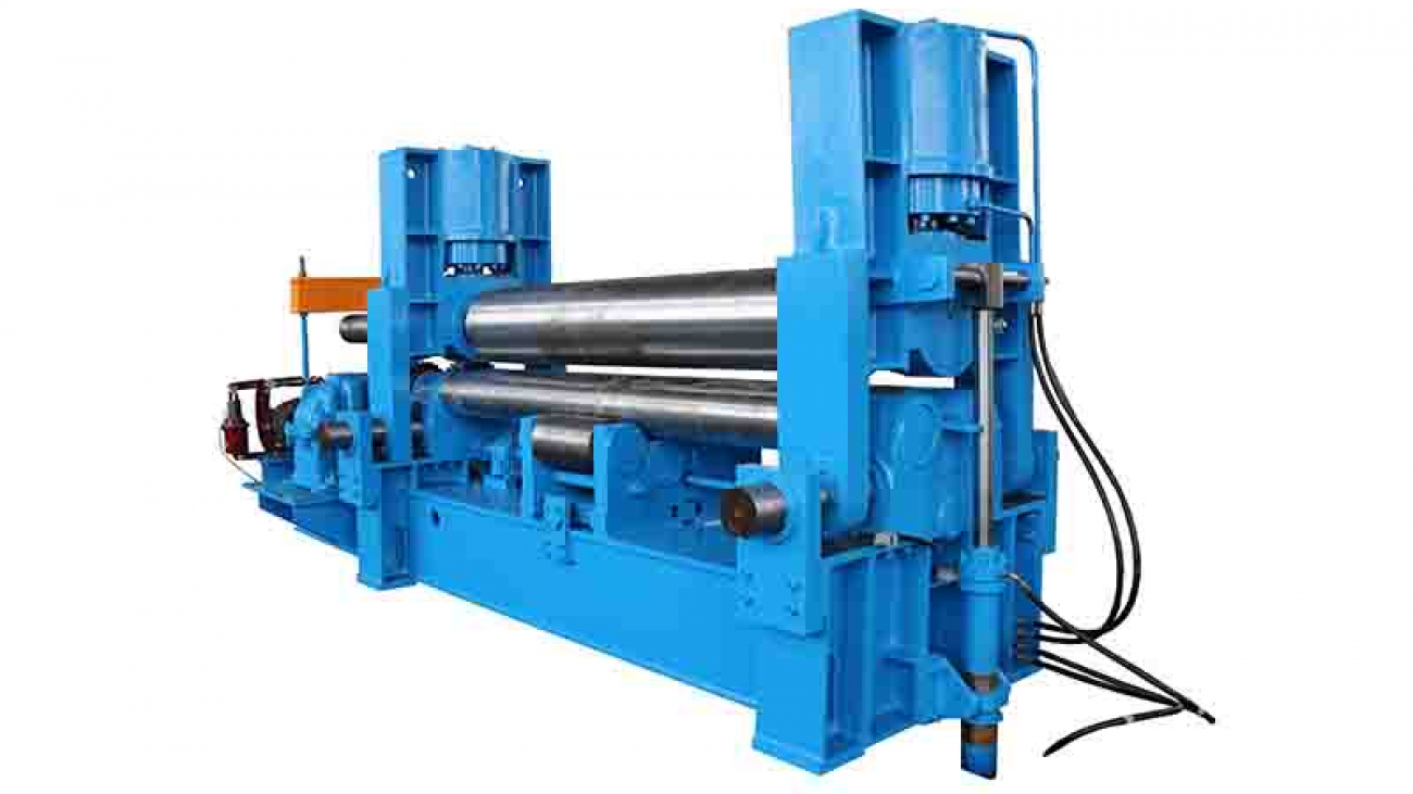
The upper roll universal rolling machine adopts hydraulic transmission for moving the upper roll, hydraulic transmission for the horizontal movement of the lower roll, and electric centralized control operating system. The machine can complete the pre-bending of several rolls at both ends of the plate at one time, and it can also carry out the metal plate. Certain plastic leveling, direct pre-bending, save trouble, save materials, configuration, system control, and improve the degree of automation. This machine is widely used in processing with high precision requirements.


Classification


Universal rolling machines are divided into: large, medium and small.


  • Large upper roll universal plate rolling machine

The main features of the large upper roll universal bending machine: unique bending process with superior product accuracy, high-precision end pre-bending, continuous bending without back angle, digital control of the bending process, man-machine dialogue control interface, efficient and intelligent operation of the physical bending process software, Man-machine dialogue window, automatic compensation during bending. Single-person operation, efficient, safe, convenient and rich in curved shapes with rolled O-shaped, U-shaped, multi-segment R and other different shapes.


  • Medium-sized upper roller universal plate rolling machine

The main features of the medium-sized upper roll universal bending machine: unique bending process with superior product precision, high-precision end pre-bending, continuous bending without back angle, digital control of the bending process, man-machine dialogue control interface, efficient and intelligent operation of the physical bending process software, Man-machine dialogue window, automatic compensation during bending. Single-person operation, efficient, safe, convenient and rich in curved shapes with rolled O-shaped, U-shaped, multi-segment R and other different shapes.


  • Small upper roll universal plate rolling machine


The main features of the small upper roll universal bending machine: unique bending process with superior product precision, high-precision end pre-bending, continuous bending without back angle, digital control of the bending process, man-machine dialogue control interface, efficient and intelligent operation of the physical bending process software, Man-machine dialogue window, automatic compensation during bending. Single-person operation, efficient, safe, convenient and rich in curved shapes with rolled O-shaped, U-shaped, multi-segment R, etc. [1].


Technical characteristics of the upper roll universal rolling machine


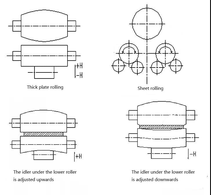
  • The drum-shaped upper roller and the lower roller under the lower roller are coordinated and adjusted to achieve high-precision product straightness


Adopting drum-shaped upper roller.The upper roller drum-shaped preset amount is generally 70% of the uniformly distributed load of the roller. The lower roller with a smaller diameter is supported by an up-and-down adjustable idler roller at the lower part of the lower roller. According to the load of the rolled product, adjusting the idler under the lower roller greatly improves the straightness of the product.


Universal plate rolling-Coordination and adjustment of the lower roller of the lower roller


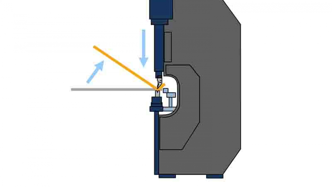
  • Curved and rolled rear, high-precision roundness


The upper roll universal rolling machine adopts rear bending (the feeding direction of the sheet is opposite to the moving direction of the upper roll). The upper roll is pressed down while the lower roll rotates, continuously bending, and the end of the sheet is directly pre-bent. , to avoid the generation of the front bend angle, and can control the length and shape of the remaining straight sides.


Generally, the three-roll asymmetric type adopts forward bending. First, the two ends of the sheet are pre-bent, and then symmetrically rolled into shape. Skilled operators are required. The product has a back angle and the shape of the remaining straight edges is difficult to control.


  • Reduce the amount of product misalignment


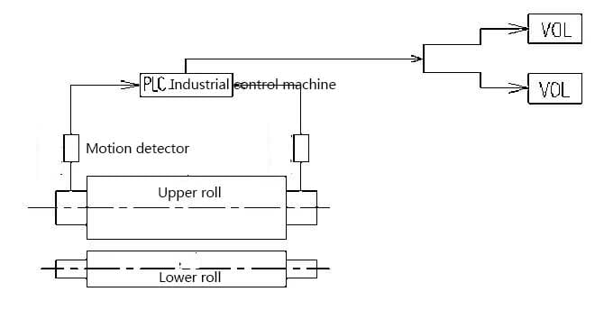
The upper roll universal rolling machine has taken the following measures to reduce the amount of product misalignment:

①The dimensional accuracy and shape tolerance of the center distance between the two lower rollers and the two lower rollers are used as key process control;

②The synchronous electro-hydraulic combination of the upper roller adopts a feedback system to automatically level.


The upper roll universal bending machine reduces the amount of product misalignment


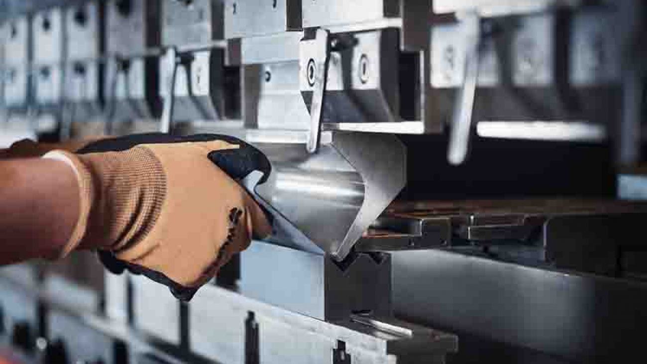
  • High-precision end pre-bending

When the end is pre-bending, the horizontal movement of the upper roller can be changed, and the length of the straight side can be set freely; the upper roller is directly pressurized to control the shape of the straight side to achieve high-precision end pre-bending.


Scope of Application


The machine is widely used in industries with high precision requirements, such as: aviation, nuclear power and other metal structural parts manufacturing industries and chemical machinery, offshore oil platforms, oil, gas and water pipelines and other industries.

V groove of the lower die

The angle of the CNC press brake is not enough and the adjustment data is invalid. What is the reason?

The angle of the CNC press brake is not enough and the adjustment data is invalid. What is the reason?


There are only two possibilities for the bending angle not to copy in place:
1 The V groove of the lower die is too small. Generally, it is calculated as six times the thickness of the material. For a material of 1mm, a groove with a width of 6mm is used.
2 The down depth of the machine slide is not enough. The adjustment data is invalid because it is input into the CNC system and the execution of the system is invalid, or the system is executed and it has no effect when controlling the machine.
If it is an electro-hydraulic servo CNC bending machine, you can observe the grating ruler to see if the downward depth changes after adjustment.
If it is a torsion-axis CNC bending machine, you can manually adjust the Y-axis position to see if there is any change.

sheet metal bending formation

Analysis of the relationship between bending formation and grooving process

Analysis of the relationship between bending formation and grooving process


The traditional bending process is to use the two edges at the opening of the lower die and the top edge of the upper die to bend the metal sheet under the pressure of the upper and lower molds of the NC press brake. The sheet metal undergoes elastic deformation to plastic deformation. The bending angle is determined by the depth of the upper mold entering the lower mold. In today’s society, people have higher and higher requirements for the shape of the workpiece. Some workpieces with complex shapes can no longer be bent using traditional free bending, bending machine bending or even three-point bending technology, and traditional bending methods cannot control the bending. The radius of the rounded corners makes it difficult to achieve the process requirements for seamless bending. Therefore, a new type of bending process-grooving bending process came into being.

It can be seen from the bending process that the size of the edge arc radius of the workpiece after bending is in direct proportion to the thickness of the sheet. The thicker the sheet, the larger the radius of the arc formed by bending. After V-grooving the metal sheet, the remaining thickness of the sheet becomes half of the original thickness, or even smaller, so that the edge arc radius after the workpiece is bent can be greatly reduced. In addition, since the remaining thickness of the bend is thinner after grooving, the deformation force during bending will be reduced accordingly, and will not spread to the unbent area. Therefore, there are no creases on the surface of the workpiece after bending, and due to bending The thickness of the board is thinner, and the pressure required during bending is reduced to avoid the risk of indentation on the decorative surface. In this way, the metal decoration of high-end places such as hotels, banks, commercial centers, airports, etc., has a small arc radius of the workpiece edge, no creases on the surface, and no indentation on the decorative surface.

In the bending process, the required bending force of the sheet metal is proportional to its thickness. The greater the thickness of the sheet metal, the greater the bending force required, and the required equipment tonnage increases accordingly. After V-shaped grooving is performed on the bending part of the sheet metal before bending, the remaining thickness of the sheet at that place is greatly reduced, so that the bending force required when the sheet is bent will also be correspondingly reduced, so that the thick plate can be in a smaller tonnage Bending on the bending machine. This not only reduces the investment in equipment, but also saves energy and space.

How to avoid the deviation of bending angle and size

For the bending process, the quality of bending mainly depends on the two important parameters of bending angle and size. When bending, in order to ensure the forming size and angle of the bending, the following issues need to be paid attention to.

⑴ The upper and lower molds are not aligned with each other, which will cause errors in the bending dimensions. The upper and lower mold tools need to be aligned before bending.

⑵ After the left and right positions of the rear stopper are moved, the relative position of the sheet metal and the lower die may change, which will affect the bending size. The position distance of the rear stopper must be re-measured before bending.

(3) Insufficient parallelism between the workpiece and the lower die will cause bending springback and affect the bending angle. The parallelism must be measured and adjusted before bending.

⑷ When the angle of the first bending is insufficient, the second bending will also be affected. The accumulation of bending errors will increase the forming size and angle errors of the workpiece. Therefore, it is particularly important to ensure the accuracy of single-sided bending.

⑸When bending, the size of the lower die V port is inversely proportional to the bending pressure. When processing metal plates of different thicknesses, you need to select the appropriate lower die V-groove according to the regulations. Generally, 6-8 times the plate thickness is the most appropriate .

⑹ When the workpiece is bent on the bending machine after planing the V-shaped groove, ensure that the edge of the upper die, the bottom edge of the V-shaped groove of the workpiece and the bottom edge of the V-shaped groove of the lower die are on the same vertical surface.

⑺ When bending the workpiece after grooving, in order to prevent knife clamping, the upper die angle is best controlled at about 84°.

grooving process, as a new type of bending process, is the result of market choice. With the continuous development of process technology, enterprises have higher and higher requirements for process personnel. As craftsmen, only by mastering various processing techniques can we produce better products; only by constantly exploring and pursuing new techniques can we produce better products.

hydraulic system

3 minutes to help you analyze and let you understand the hydraulic system of the CNC press brake

3 minutes to help you analyze and let you understand the hydraulic system of the CNC press brake


The CNC press brake is a widely used bending machine, which has already been hydraulicized. As an important piece of sheet metal processing equipment, bending machines play an irreplaceable role and play a decisive role in product quality, processing efficiency, and accuracy.

Generally, the bending machine is an upper piston press, which is composed of a frame, a sliding block, a hydraulic system, a front support frame, a back gauge, a mold, and an electrical system, as shown in Figure 1.

Two parallel working hydraulic cylinders form vertical downward pressure to drive the mold on the bending beam to perform bending work. As the brain of the bending machine, the hydraulic control system mainly controls the synchronous operation of the bending process and the positioning of the hydraulic cylinder when the machine is working at full load. I will take a certain type of universal bending machine as an example to analyze the hydraulic system.

Hydraulic system

Figure 2 shows the hydraulic system of the press brake. (The picture is a little fuzzy in the article, you can pay attention to my headline number, and privately write me the following text “hydraulic system”, you will receive a clear picture) Every time a bending action is performed, the typical bending process movement cycle stage of the upper bending beam include:

⑴Oil pump start

The motor rotates in the direction marked by the arrow of the pump, that is, clockwise, driving the axial piston pump to run. The oil enters the valve plate and the electromagnetic overflow valve return tank through the pipeline. When the No. 19 valve is closed, the No. 20 cylinder lower chamber The oil keeps the slider at a fixed position.

⑵ downward movement

The rapid downward movement of the bending machine is generated by the weight of the bending machine beam and various accessories and the pressure of the oil. During this process, the rodless cavity of the hydraulic cylinder is filled with oil through the filling valve. The rod cavity will generate back pressure and the oil will flow back quickly. The fast-forward movement starts from the top dead center. After a short deceleration stage, the speed of the slider slows down at a certain distance close to the bent sheet.

When No. 9 YV1, No. 24 YV6, No. 13 YV4, No. 17 YV5 electromagnets work, the slider quickly descends, and the descending speed is adjusted by the No. 18 valve. The oil in the lower chamber of the No. 20 cylinder passes through No. 19, No. 18, and No. 17 No. enters the oil tank, and the oil in the upper cavity of cylinder 20 is injected through the No. 21 valve.

When the slider is lowered to the limit switch, the No. 9 YV1, No. 8 YV2, No. 11 YV3, No. 13, YV4, and No. 24 YV6 electromagnets work, and the slider enters the working speed. If the slider is not synchronized, it is automatically corrected by the No. 15 valve, and the sliding position of the slider is limited by the mechanical stop in the cylinder.

⑶ bending

The bending phase starts with pressure build-up in the rodless cavity. On the one hand, the bending speed is limited by the oil supply of the oil pump, and on the other hand, it can be adjusted by the proportional valve directional valve. At the same time, the directional valve also controls the synchronous operation of the bending beam and the positioning of the bottom dead center. The limit of the bending force is accomplished by the proportional relief valve to limit the pressure of the pump. The corresponding given values of speed, synchronization, positioning and pressure all come from the CNC.

Control by foot switch or button No. 9 YV1, No. 8 YV2, No. 11

YV3, No. 13 YV4, No. 24 YV6 electromagnets work for the length of time to realize the jog distance when the slide is lowered. The speed of the slide is adjusted by the No. 16 valve, and the slide upward is controlled by the No. 11 YV3 and No. 24 YV6. The working time of the electromagnet realizes the upward jog distance of the slider.