combined punching and shearing machine

Inspection methods of Combined punching and shearing machine

Inspection methods of combined punching and shearing machine


First of all, the surface of the cutter board should not be uneven, and the joint of the door and the cover should be leveled. All components shall be internally lapped and painted, and the painted surface shall be smooth, uniform in color and free from wrinkles and appendages. Secondly, the transmission gear should be greased again. Move the cutter board by hand to check whether each part can operate normally.

If there is no problem, you can start the high-voltage electric shock, high speed to see if it can also run, two to four hours to see if the temperature of the rolling bearing is less than 63 degrees.

Combined with punching and shearing machine and mechanical profile punching and shearing machine, it integrates punching, plate shearing, angle steel shearing, profile shearing and other capabilities. Combined with the advantages of light weight, small volume and low noise, punching and shearing machine is an ideal equipment for modern machinery manufacturers, such as metallurgy, bridge, communication, electric power and other industries.

In order to meet the needs of real production, the new combined punching and shearing machine independently designed a multi-capacity hydraulic combined punching and shearing machine, in order to reach the net surface more neat and smooth, good-looking, small rib mark, high added value.

3 roller plate bending machine

Pollution control and purification of hydraulic oil for 3 roller plate bending machine

Pollution control and purification of hydraulic oil for 3 roller plate bending machine

1、Pollution control of hydraulic oil in 3 roll plate bending machine

The working life and reliability of hydraulic components are mainly determined by the pollution tolerance of components and the pollution degree of hydraulic oil of three roll bending machine. In order to ensure the service life and reliability of components, the pollution control measures can be taken to achieve a reasonable balance between the pollution degree of hydraulic oil and the pollution tolerance degree of key hydraulic components, which is the basic content and purpose of pollution control.
There are two ways to improve the working life and reliability of components: one is to develop pollution resistant components to improve the pollution resistance of components by improving the design parameters, structure and material of components; The second is to take pollution control measures to reduce the degree of pollution of hydraulic oil in three roll bending machine. Experience shows that the latter is a more economical and effective way.

In order to effectively control the pollution of the hydraulic system, the following measures are mainly taken: 1) cleaning the components and system, removing the residual pollutants in the process of processing and assembly. 2) Take measures to prevent pollutants from invading the system and control pollutants from outside. 3) High efficiency oil filter is used in the hydraulic system to continuously filter out the pollutants generated inside and intruded from outside.

2、 Purification of hydraulic oil for 3 roll plate bending machine

Prolonging the service life of the hydraulic oil of the three roll bending machine can not only save the cost of replacing the hydraulic oil of the three roll bending machine, but also save the oil resources. At present, due to the imperfect pollution control measures in some industrial sites, the hydraulic oil of the three roll plate bending machine in the hydraulic system is seriously polluted, which affects the normal operation of the equipment. Therefore, the method of frequently changing the oil has to be adopted. In fact, the dirty oil replaced is only polluted beyond the limit, and the physical and chemical properties do not reach the degree of deterioration. This kind of hydraulic oil can still be used after proper treatment. The experience shows that improving the cleanliness of hydraulic oil of three roll plate rolling machine through pollution control can significantly delay the deterioration of hydraulic oil performance of three roll plate rolling machine, and the service life of hydraulic oil of three roll plate rolling machine can be extended by 3-5 times. The Japanese industry has put forward that the service life of the hydraulic oil of the three roll bending machine can be extended to 10 years through the purification measures of the hydraulic oil.

Purification methodPrincipleApplication
filterThe use of porous media to filter out insoluble substances in oilSeparation of solid particles
centrifugalThe fluid can be moved in a circular way by mechanical means of separating insoluble substances with different density by using the radial acceleration generatedSeparation of solid particles and free water (centrifuge)
inertiaThe oil can move in a circle by hydraulic pressure, and the insoluble substances with different density can be separated by radial accelerationSeparation of solids and free water (cyclone)
magneticUsing magnetic force to absorb ferromagnetic particles in oilSeparation of ferromagnetic particles and debris
static electricityThe insoluble pollutants in insulating oil are adsorbed on the dust collector in electrostatic field by electrostatic field forceSeparation of solid particles and colloidal substances
vacuumUse the difference of saturated vapor pressure under negative pressure to separate other liquids and gases from oilSeparate free and dissolved water, air and other volatile substances
CoalescenceBased on the difference of wettability (or affinity) of liquid to a porous medium, the mixture of two insoluble liquids is separatedSeparation of free water and emulsified water from oil
adsorbentSeparation of soluble and insoluble substances in oil by molecular adhesionSeparation of solid particles, various states of water, colloidal substances
hydraulic ironworker machine

Advantages and basic operation of hydraulic ironworker machine

Advantages and basic operation of hydraulic ironworker machine


Hydraulic ironworker machine integrates intelligent mechanical equipment, mainly including metal cutting, steel plate processing, punching machine, and sheet metal bending. It is easy to use in the operation process, low energy consumption, low maintenance cost, and effectively saves the investment of assets. It is an ideal equipment for precision processing in intelligent processing industry; It is widely used in steel structure processing, hardware processing, grain machinery shell and large parts processing, thresher template support, trailer body mechanical parts processing, etc; There are many types of punching and shearing machines in the market, including hydraulic press combined punching and shearing machine, double hydraulic press combined punching and shearing machine, etc; The equipment is compact in structure, superior in performance, exquisite in appearance, convenient in use and safe in use;

In the operation process of the hydraulic ironworker machine, the first step is to check the switching power supply, and the next step can be carried out when the air switch is intact and the working voltage is stable; Next, open the equipment wiring cabinet for wiring, and then close the cabinet door tightly; Step 4: step on the foot switch. If the device doesn’t respond, switch the power supply of the switch when the emergency stop button is turned off; Then, the power needs to be cut off when the grinding tools are removed and replaced. Finally, after the work is finished, turn off the switching power supply and remove the slag.

Advantages and characteristics of hydraulic ironworker machine:

1. With hydraulic transmission, the whole machine has reasonable structure, light weight, low noise, light and reliable, and overload performance.
2. The machine is equipped with punching station, channel steel and angle steel cutting station, thick plate cutting station, round steel and square steel cutting station and corner cutting station. Optional purchase punching large hole, plate bending, channel steel punching, shutter and pipe corner cutting accessories.
3. Standard equipped with five stations and dual hydraulic workstation. Can work independently at the same time. The machine does not need any horizontal adjustment and can be used after it is placed in place. CNC control system is optional to increase automatic punching and shearing efficiency.
4. The machine adopts European processing technology, and the whole frame is welded. After high temperature quenching, the frame has high rigidity and high strength; The cutting tool is treated by special vacuum and high temperature to prolong its service life.
5. With pipe cutting die, the pipe can be cut and beveled, with high efficiency, cost saving and beautiful cutting section.

hydraulic punching and shearing

How to reduce the noise of Hydraulic punching and shearing machine

How to reduce the noise of Hydraulic punching and shearing machine

1. Ensure that the combined punching and shearing machine is always in good technical condition.
2. Ensure the integrity and reliability of the working parts of the punching and shearing machine. In particular, the exhaust pipe should be installed well, because most of the exhaust pipes are equipped with silencers, which will reduce a large part of the noise.
3. Prevent the parts from loosening, which will cause vibration.
4. Do a good job in the maintenance and inspection of the combined punching and shearing machine. Add qualified lubricating oil and grease according to regulations to prevent dry friction or semi dry friction caused by poor lubrication of relative moving parts and increase noise.
5. Keep good fit clearance relative to moving parts. The driver must assemble or adjust according to the technical requirements.
6. Do not change the oil supply quantity at will. If the fuel supply volume becomes larger, the fuel injected into the cylinder will not burn completely, which not only wastes the fuel, pollutes the air, but also increases the noise of the tractor.
The oil supply advance angle should be adjusted accurately. The accuracy of oil supply advance angle adjustment not only directly affects the power of the combined punching and shearing machine, but also affects the noise of the combined punching and shearing machine. We often meet some combined punching and shearing machine in the emission of exhaust gas when the sound is particularly loud, often accompanied by “Pa, Pa” sound, this is because the oil supply advance angle is too large.

8mm sheet metalrolling machine for sale

8mm thickness Sheet metal rolling machine for sale,3 meter Sheet metal roller

8mm thickness Sheet metal rolling machine for sale,3 meter Sheet metal roller

Description

W11 8×3000 sheet metal rolling machine is three-roller symmetrical structure; the upper roller is driven by the lead screw and the worm gear to move in the vertical direction at the center symmetrical position between the lower two rollers. As the main driving roller for rotating motion, the two lower rollers mesh with the output gear of the reducer to provide torque for the rolling plate. The machine has a compact structure and is easy to operate and maintain; in addition, the roller is also suitable for installing profile molds to facilitate rolling of various profiles.


Features

1.European standard design

2.Three-roller symmetric structure, compact, easy operation and maintenance

3.Easy-to-use removable console

4.Two sets of digital output for easy positioning of two lower rollers

5.SAE 1050 quality certificate


Standard configuration

●Easy-to-use removable console

●The upper roller is electrically depressed through the console

●Suitable for thin and heavy plate, aluminum or stainless steel sheet rolling

●Ferrules in full circle or varying radiuses can be done easily

●Overload protection

●Two sets of digital output for easy positioning of two lower rollers

●Extended roller shafts for profile and pipe rolling operation


Safety standard

●Safety standards (2006/42 / EC)

●Open the electrical cabinet door to power off

●Domestic pedal switch ( safety grade 4 )

●Body metal safety rail conforms to CE standards

●Safety relay monitors the pedal switch, safety protection

Technical parameters

NoNameConfiguration ParameterW11-8/3000
1Max Plate Thickness<450N/mm2mm8
<700N/mm2mm5
2Max Plate Length ( A ) mm 1500(A)mm3000
3Loaded with minimum volume
plate diameter
mm550
4Yield LimitN/mm2245
5rolling speedm/min4.5
6Upper Roller Diametermm240
7Lower Roller Diametermm180
8Lower Roller Center Distancemm280
9Main Motor Powerkw7.5
10Length(A)mm5100
11Width(B)mm950
12Length(H)mm1250
13WeightKG4300
8mm plate rolling machine for sale

8mm thickness Plate rolling machine for sale,2 meter Sheet metal roller

8mm thickness Plate rolling machine for sale,2 meter Sheet metal roller

Description

W11 8×2000 plate rolling machine is three-roller symmetrical structure; the upper roller is driven by the lead screw and the worm gear to move in the vertical direction at the center symmetrical position between the lower two rollers. As the main driving roller for rotating motion, the two lower rollers mesh with the output gear of the reducer to provide torque for the rolling plate. The machine has a compact structure and is easy to operate and maintain; in addition, the roller is also suitable for installing profile molds to facilitate rolling of various profiles.


Features

1.European standard design

2.Three-roller symmetric structure, compact, easy operation and maintenance

3.Easy-to-use removable console

4.Two sets of digital output for easy positioning of two lower rollers

5.SAE 1050 quality certificate


Standard configuration

●Easy-to-use removable console

●The upper roller is electrically depressed through the console

●Suitable for thin and heavy plate, aluminum or stainless steel sheet rolling

●Ferrules in full circle or varying radiuses can be done easily

●Overload protection

●Two sets of digital output for easy positioning of two lower rollers

●Extended roller shafts for profile and pipe rolling operation


Safety standard

●Safety standards (2006/42 / EC)

●Open the electrical cabinet door to power off

●Domestic pedal switch ( safety grade 4 )

●Body metal safety rail conforms to CE standards

●Safety relay monitors the pedal switch, safety protection

Technical parameters

NoNameConfiguration ParameterW11-8/1500
1Max Plate Thickness<450N/mm2mm8
<700N/mm2mm5
2Max Plate Length ( A ) mm 1500(A)mm2000
3Loaded with minimum volume
plate diameter
mm400
4Yield LimitN/mm2245
5rolling speedm/min4.5
6Upper Roller Diametermm180
7Lower Roller Diametermm170
8Lower Roller Center Distancemm250
9Main Motor Powerkw5.5
10Length(A)mm3500
11Width(B)mm850
12Length(H)mm1150
13WeightKG2500


8mm plate rolling machine

8mm thickness Plate rolling machine for sale,1.5 meter Plate roller

8mm thickness Plate rolling machine for sale,1.5 meter Plate roller

Description

W11 8×1500 plate rolling machine is three-roller symmetrical structure; the upper roller is driven by the lead screw and the worm gear to move in the vertical direction at the center symmetrical position between the lower two rollers. As the main driving roller for rotating motion, the two lower rollers mesh with the output gear of the reducer to provide torque for the rolling plate. The machine has a compact structure and is easy to operate and maintain; in addition, the roller is also suitable for installing profile molds to facilitate rolling of various profiles.


Features

1.European standard design

2.Three-roller symmetric structure, compact, easy operation and maintenance

3.Easy-to-use removable console

4.Two sets of digital output for easy positioning of two lower rollers

5.SAE 1050 quality certificate


Standard configuration

●Easy-to-use removable console

●The upper roller is electrically depressed through the console

●Suitable for thin and heavy plate, aluminum or stainless steel sheet rolling

●Ferrules in full circle or varying radiuses can be done easily

●Overload protection

●Two sets of digital output for easy positioning of two lower rollers

●Extended roller shafts for profile and pipe rolling operation


Safety standard

●Safety standards (2006/42 / EC)

●Open the electrical cabinet door to power off

●Domestic pedal switch ( safety grade 4 )

●Body metal safety rail conforms to CE standards

●Safety relay monitors the pedal switch, safety protection

Technical parameters

NoNameConfiguration ParameterW11-8/1500
1Max Plate Thickness<450N/mm2mm8
<700N/mm2mm5
2Max Plate Length ( A ) mm 1500(A)mm1500
3Loaded with minimum volume
plate diameter
mm380
4Yield LimitN/mm2245
5rolling speedm/min5
6Upper Roller Diametermm170
7Lower Roller Diametermm160
8Lower Roller Center Distancemm220
9Main Motor Powerkw5.5
10Length(A)mm3050
11Width(B)mm900
12Length(H)mm1150
13WeightKG2400


what is a hydraulic ironworker machine

What is a hydraulic ironworker machine

What is a hydraulic ironworker machine

Description

The hydaulic ironworker machine is a kind of machine tool equipment that integrates multiple functions such as metal cutting, punching, shearing, bending, etc. It has the advantages of simple operation, low energy consumption, and low maintenance cost. It is a modern manufacturing industry (such as: Metallurgy, bridges, communications, electric power, military and other industries) metal processing equipment of choice. Ironworker Machines are divided into hydraulic Ironworker Machines and mechanical Ironworker Machines, of which hydraulic type is the most widely used. The Hydraulic Ironworker Machine is generally suitable for processing small workpieces, and can work in multiple stations at the same time. The left foot switch individually controls the punching station, and the right foot switch controls the operation of other jobs at the same time.

Feature

The punching function is located at the left station of the Hydraulic Ironworker Machine and is controlled by the left foot switch. By changing different upper and lower molds, holes of different sizes and shapes can be punched. Each set of die has a certain life time, and the die needs to be replaced after the service life is exceeded. If the punching and shearing machine model is Q35Y-20, 20 is the maximum shearing thickness of 20mm.

The Hydraulic Ironworker Machine is widely used in:

1. Steel structure processing

2. Elevator and parts processing

3. Trailer—spare tire parts, trailer hinges, hooks, inserts, and wall plates

4. Construction machinery industry-processing on belt conveyors and mixing stations

5. Agriculture and animal husbandry machinery industry-threshing frame body, trailer body parts processing

6. Food industry machinery-slaughter equipment frame and parts processing

7. High and low voltage tower parts processing

8. Wind power equipment-parts processing on the stairs and pedals on the wind power tower

9. Machining-processing of building embedded parts, conveyor brackets and other parts that play a role in connection

10. Grain machinery-grain and oil equipment, starch equipment support, shell, small parts processing

11. Processing of railway wagons, automobiles and crane parts 12. Channel steel, square steel, round steel, H steel, I-beam and other steel materials cutting, punching, bending.

Operations

Before starting the machine, check whether the transmission parts of the punching and shearing machine and the connecting screws and pins are loose. Whether the electrical grounding is intact. 2. Lubricate the various parts before work, and start the trial run for two to three minutes before starting work without any problems. 3. Overload is not allowed, and punching and shearing of quenched steel is strictly prohibited. 4. Wear gloves and labor protection equipment when working. Sandals and slippers are strictly prohibited. 5. When punching and cutting, always add oil to the punch to prevent the upper and lower punch from skewing. 6. Pay attention to the safety of your }ngers when feeding the material, especially when the sheet material is not pressed by the presser foot at the end, punching is prohibited. 7. It is strictly forbidden to disassemble and proofread the cutting edge and punching die when starting up. Don’t hit punches, shears and other parts with force. 8. Strictly control the speci}cation range of the sheet material, and it is strictly forbidden to punch and cut when it exceeds. 9. The workplace must not accumulate other objects and a large amount of ~ushing materials, and must stop during adjustment and cleaning. 10. After the work is completed, shut down and cut off power in time to clean up the site.

Maintenance

1. Operate strictly in accordance with the operating procedures. 2. Add lubricating oil according to the requirements of the lubrication chart every time before starting up. The oil should be clean and free of precipitation. 3. The shearing machine must be kept clean frequently, and the unpainted part must be rust-proof grease. 4. The lubricating oil in the motor bearing should be replaced and re}lled regularly, and the electrical part should be regularly checked for normal, safe and reliable operation. 5. Frequently check whether the V-belt, handle, knob and button of the shearing machine are damaged. If they are severely worn, they should be replaced in time, and the spare parts should be reported for supplement. 6. Regularly check and repair switches, insurances, and handles to ensure reliable operation. 7. 10 minutes before the end of the day, lubricate and scrub the machine tool.

plate rolling machine

How to choose the right plate rolling machine for your needs

How to choose the right plate rolling machine for your needs


Although it is one of the most complicated fabrication processes, plate rolling is essential if you want to provide your customers with more bending options. However, unlike a press brake, which delivers a single bend in one direction of inertia, a plate rolling machine features multiple forces and different courses when the plate rolling process is taking place.

Plate rolling is an art, which needs an experienced operator who understands how to control all the intricacies of this sophisticated piece of equipment and the reaction the material he is working with will have. But besides having a skilled operator, it is also crucial that you match the right machinery to a particular job. This article provides some insightful tips on how to select the best plate roll for your plate rolling project.

For you to know which plate roller best fits your projects, you need to answer these questions:

Which types of materials will you be working with?

The first thing you need to do before you start searching for the best plate roll bender is to determine the type of materials you will be using in your project. Here, you’ll have to consider things such as thickness, width, diameter, strength and yield. These elements determine the amount of pressure you’ll need and the max and min diameter and width of the plate roller you’ll use.

What’s the minimum diameter?

Taking the thickest material you will be working and the minimum diameter you will be rolling that material down to will help determine the plate roll size. Plate rolls generally use the 1.5 rule, meaning that a diameter rolled can be no less than 1.5X the top roll diameter. Knowing the minimum diameter you need along with the yield strength of the material is critical in selecting the right plate roll.

Are you rolling only round objects or are you rolling out-of-round?

Any plate roll can produce the required round cylinders but when special shapes are required it takes a machine equipped with a CNC control to manipulate the rolls position in conjunction with the desired speed that the rolls are turning. Whether you’re rolling ovals such as fuel tanker trailer skins or some oyster non-round shape a CNC control will take all the guesswork out of roll speed and roll positions.

How large a diameter are you producing?

The larger the diameter rolled the more the need for additional supports around the plate roll. Most manufacturer’s offer side supports as an option to support the sheet being fed into the rolling process. However your application may also call for an overhead support if a large radius is required and the rolled sheet is being sent high into the air. The combination of side and overhead supports can assist in supporting the sheet during the process and avoid any back bending caused by the unsupported weight of the material itself.

How much are You producing?

For you to get the best plate roller machine, you need to know the quantity of your output. This will help you determine the type of plate roll machine that will resonate with these needs. The three and four roll machines are considered to be the best for massive projects, but they boast distinct operational complexity, accuracy levels, and features. You’ll have to choose whether you’ll prefer the three roll machines that are known for their versatility and affordability, or the four roll machines, which are swift, accurate, and precise.

ironwoker machine principle

Hydraulic ironworker evolution history

Hydraulic ironworker evolution history


The hydraulic ironworker was originally invented in 1949, but it never really entered the scene until 50 years ago when the patent was acquired and manufacturing of these metal fabricating machines in the U.S. began. Many of the earliest models are still operational on shop floors and in maintenance departments today.

For example, the first model produced by Scotchman was the 314, and we continue to get calls for replacement parts for that model. The original design was a hydraulic system, but it was powered only in one direction. It had a spring return. When the punch was engaged, the ram went down, and the spring pulled it back up. That coil spring was similar to one found in a ’57 Chevy at the time.

Fifty years later, we continue to sell dozens of those springs per month. So we buy the spring, compress it, and weld a frame around it for delivery to the customer. When the fabricator gets it, he drops it into the ironworker and cuts the frame to expose the compressed spring. That old hydraulic ironworker is ready for more work.

That’s no surprise. It’s a testament to how those ironworkers were made.

Mechanical ironworkers also were made to be long-lived. Unfortunately, they were very large, and while they still were somewhat functional, they ultimately found their way to the scrap heap to make way for more modern equipment.

Older hydraulic equipment didn’t stand out as much because it was smaller than the mechanical counterparts in many instances, yet it was able to deliver similar, if not more, force. As a result, these tools remained in use and avoided a second life as a boat anchor.

Hydraulic ironworkers may still look similar to those early models made a half-century ago, but they have evolved in several ways. It’s one of the reasons that companies keep placing orders for them and finding new ways to put them to use in manufacturing and maintenance settings.

Safety First and Always

In the late 1960s, when hydraulic ironworkers appeared on the scene, much larger mechanical models dominated the shop floor. Those mechanical ironworkers had huge flywheels that, when triggered, brought down the ram in a powerful and dramatic way. However, once it was triggered, nothing was going to stop it. It was going to come down and then go back up.

Those early hydraulic ironworkers could deliver similar force, but didn’t require all of the weight that the mechanical ironworkers did. However, you still had to respect the tonnage and power of the machine, even if it were smaller.

Modern hydraulic ironworkers have complete control of the entire stroke—both up and down. An emergency stop results in a halting of the fabricating or shearing action—unlike those older mechanical ironworkers, for which it was all about tripping the flywheel and staying out of the way.

A lot of this has to do with electric controls that govern the stroke. These controls have quicker cycle times and greater authority over the stroke than mechanical linkage stroke controls. Electric stroke controls use switches that send signals to the control valve almost instantly.

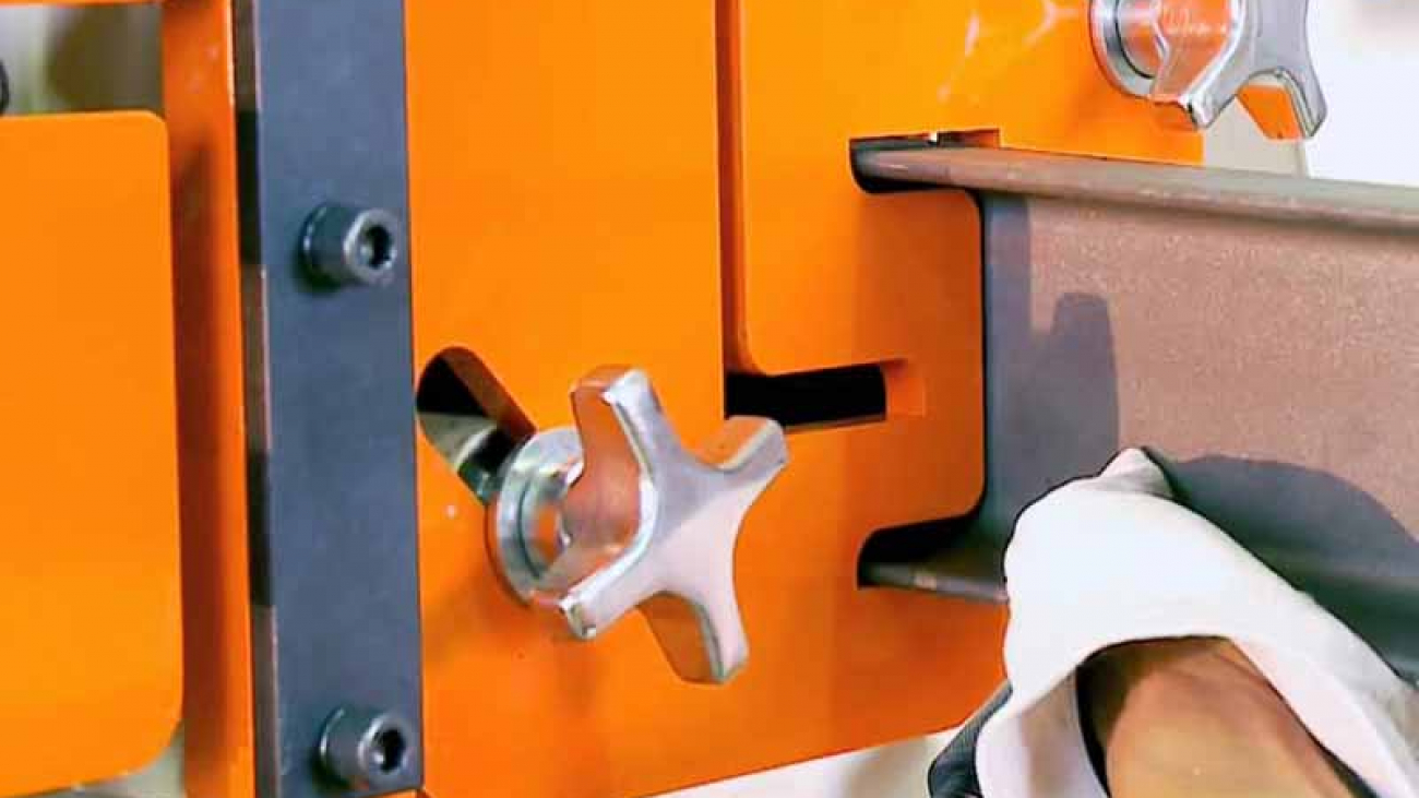
Also, the guarding standards for today’s ironworkers make it very difficult for an operator to expose his or her extremities at a pinch point of a properly designed ironworker. ANSI B11.5 standards provide the guidelines for guarding on an ironworker: It should be designed to allow material access to the machine, but prevent any part of the body from getting between the material being punched, sheared, or notched and the stripping mechanism.

Many More Options

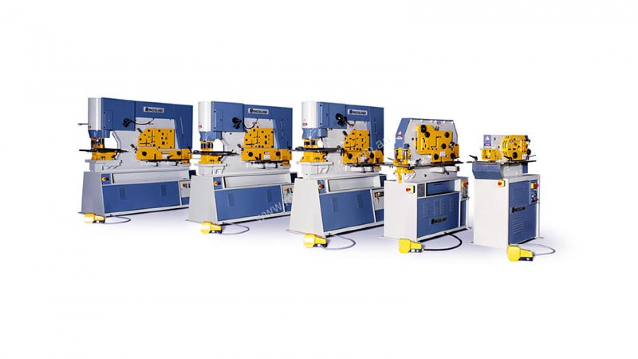
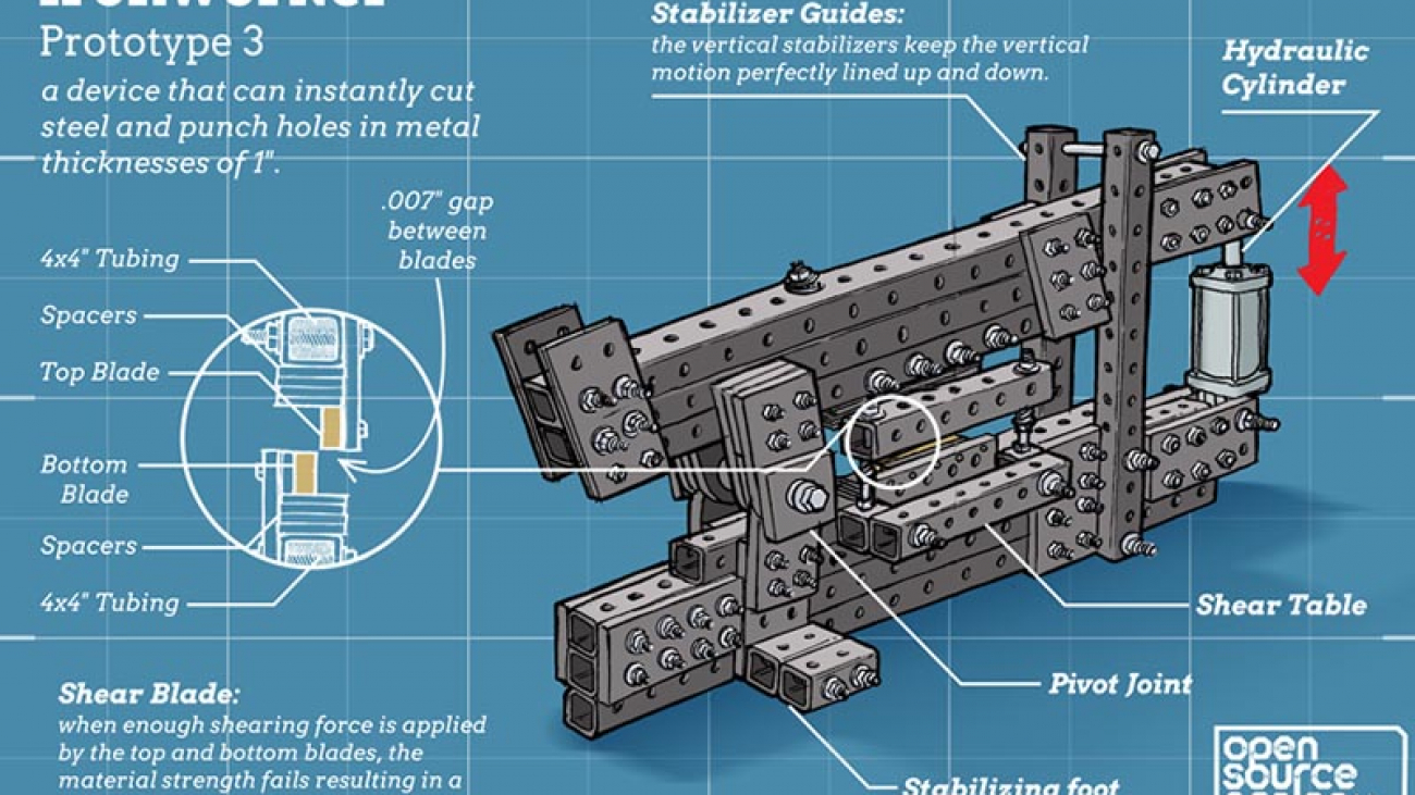
Those first hydraulic ironworkers are just like the ironworkers of today: multifunctional machines (see Figure 3). In fact, the first models had a 35-ton punch, 3-in. angle shear, and a 7-in. flat bar shear. Those same punching and shearing functions, albeit in greater tonnages now, are still pretty much available on any ironworker made in the world today.

Those higher tonnages do make a big difference. It’s not unusual to see a 150-ton ironworker punching a hole in 1.25-in. steel plate. High-powered ironworkers also can shear 1-in. plate like it was butter.

Early on, these multifunctional devices demonstrated increased flexibility with the introduction of component systems that could be added to the original equipment. For instance, a basic ironworker could have had a simple channel shear station, but that later could have been switched out for another function such as press brake bending, tube shearing, or pipe notching. These types of components are designed to be quickly changed over to keep up with the high-mix work load often found in job shops and maintenance departments.

Following a European trend, hydraulic ironworkers emerged that had these additional functions fully integrated. Fabricators didn’t have to worry about switching out components. They could have the punch, flat bar shear, rod shear, rectangle notcher, and angle shear all built into one machine. Depending on the ironworker model, a fabricator also could see one of the functions replaced with a redundant function, such as another punch, or with something different, such as a press brake or pipe notcher.

Fabricators, of course, have always been interested in cost savings, so that led to the creation of dual-operator models. Originally, the ironworkers’ hydraulic system supplied power to only one function at a time. Down the line, manufacturers engineered the hydraulic systems to allow for two functions to operate at the same time, allowing a fabricator to purchase one machine, instead of two, and double productivity compared to a one-function-at-a-time ironworker.

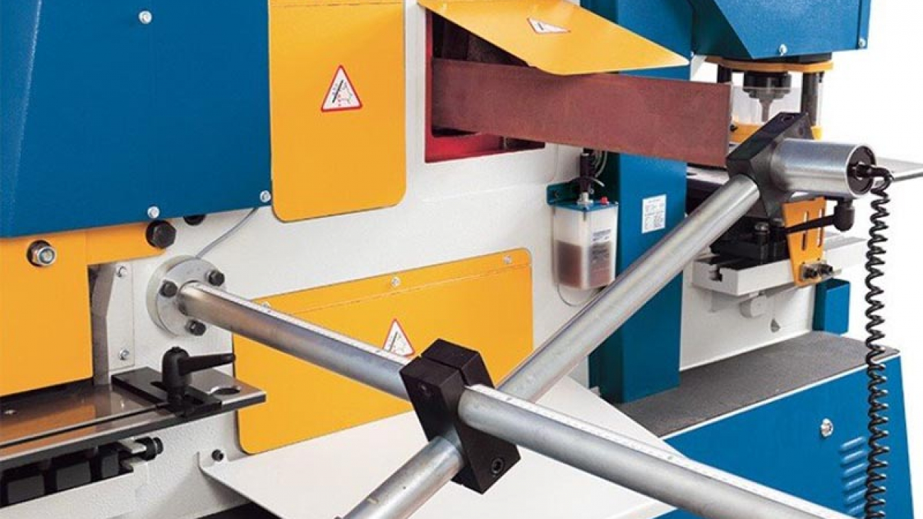
Over the past several years, fabricators also have seen the addition of programmable stop systems applied to ironworkers (see Figure 4). More commonly used on saws, these belt-driven, computer-controlled systems move material to specific lengths in between fabricating activities on the ironworker. For example, such a system can be programmed to punch 10 holes in a 10-ft. part, and once the locations are programmed into the controller, the machine completes the job without operator interference. This eliminates the need for the operator to mark the individual holes and move the part himself in between punches, making for a more efficient punching process.

This sort of automation really stands out when the hole locations do not follow a distinct pattern. With variation comes an increased chance of rework if a human is involved. Computer-controlled punching jobs boost the quality level of these types of parts.

The Ironworker’s Future

What does the future hold for this venerable piece of equipment? The hydraulic-powered ironworker’s versatility has enabled it to remain a viable tool even as manufacturing in the U.S. has moved from high-volume production to more high-mix, low-volume scenarios. If ironworkers can remain relevant after that type of shift, that bodes well for the tool’s future.

All you have to do is look at where ironworkers are used. They remain the only fabricating machine tool that can be found in the third story of New York’s Metropolitan Opera House, where they build set pieces, and also in the maintenance shops of the world’s largest automotive manufacturers. They have evolved to meet the fabricating needs of modern manufacturers, no matter where they might be or what they might do, and that likely will be the story 50 years from now as well.